

jab
-
Posts
49 -
Joined
-
Last visited
-
Days Won
1
Content Type
Profiles
Forums
Blogs
Gallery
Posts posted by jab
-
-
FantomXR - Are you willing to share the sch/brd files for the 1 piece board? I'd like to see about getting a quote on that through my network.
-
Bringing this thread back because I'm interested in a PCB like this. AND... I might be in a position to have some made, including SMT components and LCD's soldered on (or maybe connected with flex sockets). My father has been in the electronics manufacturing industry for 30+ years and I'll be visiting him in the next few weeks. I'm going to discuss what it would cost to manufacture something like this in California. Depending on the result of that discussion and if there's enough interest I may be able to do a group order.
Hey FantomXR, how close did you get with your design? I'm curious what issues you ran into and why you opted for the breakout board solution?
-
Still struggling with this... anyone have some advice for me?
-
So I got around to testing this out... wired up as I explained above, using the following in my NGC file:
DIN_MATRIX  n=1  rows=8  inverted_sel=1  sr_dout_sel1=1  sr_din1=1
DOUT_MATRIX n=1  rows=8  inverted_sel=1  sr_dout_sel1=1  sr_dout_r1=2

EVENT_BUTTON_MATRIX id=1  fwd_id=LED_MATRIX:1  type=NoteOn key=36 lcd_pos=1:1:2 label="Matrix1 Pin %2p %b"
So with this code (for testing only) I noticed that when i push a button, the button's LED lights fully (as expected) but the LED in the same column, but one row above also lights faintly.
i've double checked all my wiring and can't find anything wrong. My SEQ_V4L always worked perfectly so I feel confident in my soldering, but... Any suggestions on what to test?
-
Hey guys - I'm looking at repurposing my V4L board as a plain old button/led matrix and wanted to double check with you folks before I break something. After studying the schematic (http://www.ucapps.de/midibox_seq/mbseq_lite_blm.pdf) it seems like I should be able to make some custom cables to connect this to a DIO_matrix module. Here's what I concluded:
J5A/J5B A0-A7: connect to DOUT #1 O7-O0
J15A D0-D7: connect to DOUT #2 O7-O0
J15A Vs: connect to Vs
J10 D0-D7: connect to DIN #1 I0-I7Anyone see any issue with this? Or is there a better way to do what I'm after?
-
Is this a "closed source" design?
-
Same question! I'd like to evaluate how the SEQ would fit into my workflow before I build one.High all, I noticed Thorsten posted a virtual BLM lemur template for the SEQV4. I was wondering if something like that is theoretically possible for the panel controls(?) I couldn't find anything in the manual on sysex commands for those parameters. I would use very few of the panel controls and I'm interested in the smallest possible format for the SEQv4. i.e. I would like to control as much as possible from launchpad minis and then use the ipad just for the most essential commands. -
1 pair please
-
Well as a workaround for now, i'm going to light the buttons by default, and turn them off when pressed.
-
Hm, so if I remove the RGB parameter from the LED event, how do I set the LED to be dimmed slightly when there's the button isn't pressed?
-
Hmm, I hadn't considered that. Ok, so if I remove the dimmed parameter and try using rgb parameters in both the EVENT_BUTTON and EVENT_LED definitions like so:
EVENT_LED     id=1001  hw_id=1001  bank=1  rgb=1:0:0  fwd_to_lcd=1  lcd_pos=1:20:1    label="%3d %p"
EVENT_BUTTON  id=1001  hw_id=1001  bank=1  rgb=15:0:0 fwd_id=LED:1001  fwd_to_lcd=1  type=NoteOn key=36 chn=1 lcd_pos=1:33:2   label="%3i %N@(1:1:2)%B"
The Led is off by default and when the button is pressed, it lights up dimly (the 1:0:0) value. So it seems like the rgb value from EVENT_BUTTON will not override the EVENT_LED...
Or did I misunderstand your suggestion?
-
Hi,
you have set the first DOUT shift register in your DOUT matrix and your DIN matrix.
Hey! I was triggering both off the same DOUT which has worked fine otherwise. I tried using a different SR just in case, but no difference... :(
-
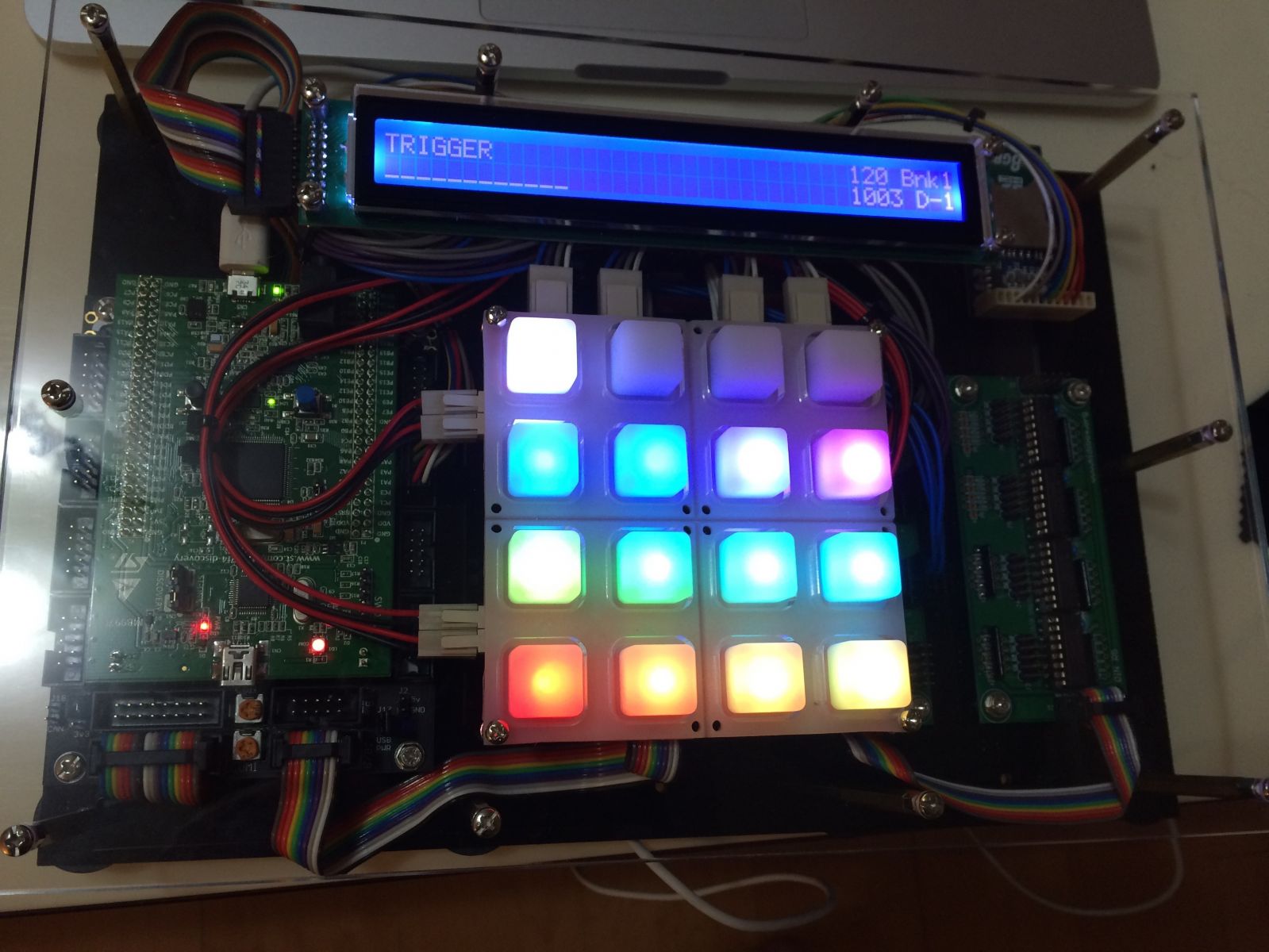
Hi folks - I have a 4x4 LED/button matrix setup for drum pads. Here's what I'm looking to set up (but can't)...
- All RGB LED's are a different color, always on but dimmed to lowest intensity
- When the respective button is pressed (or note received), the LED brightness changes to full intensity
I've tried a lot of different configs, and I can get the led's to stay dimmed until a button press, but... the color doesn't change. All the LED's stay red. The config below is what I have now:
RESET_HW

LCD "%C@(1:1:1)v1.0"

DebounceCtr 255

### SR ###

DIN_MATRIX  n=1  rows=4  inverted=0  sr_dout_sel1=1  sr_din1=1                                button_emu_id_offset=1001
DOUT_MATRIX n=1  rows=4  inverted=0  sr_dout_sel1=1  sr_dout_r1=3  sr_dout_g1=4  sr_dout_b1=5 led_emu_id_offset=1001

### Buttons ###

# LED's

EVENT_LED     id= 1001  hw_id=1001  bank=1  range=map1   dimmed=1  fwd_to_lcd=1  lcd_pos=1:20:1    label="^std_led"
EVENT_LED     id= 1002  hw_id=1002  bank=1  range=map1   dimmed=1  fwd_to_lcd=1  lcd_pos=1:20:1    label="^std_led"
EVENT_LED     id= 1003  hw_id=1003  bank=1  range=map1   dimmed=1  fwd_to_lcd=1  lcd_pos=1:20:1    label="^std_led"
EVENT_LED     id= 1004  hw_id=1004  bank=1  range=map1   dimmed=1  fwd_to_lcd=1  lcd_pos=1:20:1    label="^std_led"

# Bank 1

EVENT_BUTTON  id=1001  hw_id=1001  bank=1  fwd_id=LED:1001  fwd_to_lcd=1  type=NoteOn key=36 chn=1  rgb=15:0:0    lcd_pos=1:33:2   label="%3i %N@(1:1:2)%B"
EVENT_BUTTON  id=1002  hw_id=1002  bank=1  fwd_id=LED:1002  fwd_to_lcd=1  type=NoteOn key=37 chn=1  rgb=15:2:0    lcd_pos=1:33:2   label="%3i %N@(1:2:2)%B"
EVENT_BUTTON  id=1003  hw_id=1003  bank=1  fwd_id=LED:1003  fwd_to_lcd=1  type=NoteOn key=38 chn=1  rgb=15:8:0    lcd_pos=1:33:2   label="%3i %N@(1:3:2)%B"
EVENT_BUTTON  id=1004  hw_id=1004  bank=1  fwd_id=LED:1004  fwd_to_lcd=1  type=NoteOn key=39 chn=1  rgb=12:12:0   lcd_pos=1:33:2   label="%3i %N@(1:4:2)%B"

MAP1  1  2  3  4  5  6  7  8  9 10 11 12 13 14 15
What am I doing wrong, or is there a better way to do this?
-
Very nice work! Do you have more pictures of the construction?
And what other equipment did you use to make the track?
-
Rather than designing a whole new board, that replicates the functionality of all the existing modules, what about creating a tray/sled that bolts to the case, and aligns all the board connectors flush to the backplate? It could be laser cut from acrylic/aluminum sheet (or printed out as a 1:1 stencil for manual drilling at home) and probably wouldn't need to be very thick to be strong enough... If I had good dimensions for the parts involved I could sketch out something like that pretty quickly. Thoughts?
-
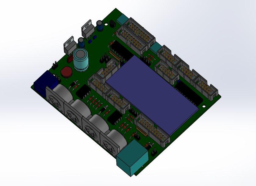
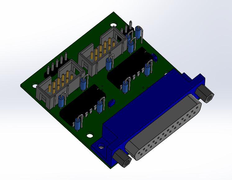
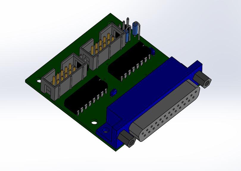
I'm still working on these, a friend was able to export the CORE_LPC17 project file (made in altium unfortunately) into an EMN/EMP file that I can import through solidworks. It's a little rough around the edges, but with some cleanup and hacking I've been able to put together something quite usable for my case/project design purposes.
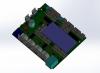
All that's really missing are to confirm the dimensions on the pots and the USB/ETH connectors. I've found that this gets easier once I have a library of models for the components made up. I was able to take TK's new Line driver and make up finished assemblies rather quickly:
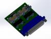
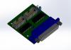
Not sure how many folks are interested in these models, but I guess I need to get registered on the wiki and start packaging these up for download.
Novski - I was clearing my inbox and found a digest mail sent before the server crash. I like your suggestion on how to make up DIN/DOUT models, thanks for the idea!
Edit: Note to self, must save these as better quality jpg files...
-
x3
Thanks and nice work TK!
-
Thanks TK, I can see how that is not the intended use case for the lite. And sorry if It seemed like I was asking for a new custom feature that only benefits me - I've never had a sequencer like this before so I'm still learning how to do things!
-
Hi folks -
Hope i'm not missing the obvious here, but i have a copy/paste question:
I can copy/paste from Seq1 to Seq2 no problem. But if I have a 16 step pattern in bar 1, Is it possible to copy/paste to bar 2, and then change the length to 32 steps? Or is this sort of functionality achieved in a different way?
Edit: for clarification, I'm looking to record a 1 bar pattern, and duplicate it to bars 2,3,4, so then i can add different notes to the different bars.
Thanks!
-
Hi folks -
Is there an available gerber, .dxf or other mechanical/mcad file detailing the component holes on this pcb?
Correct me if I'm wrong, but it looks like the board layout is not public? I bought a board from SmashTV so I don't strictly need the board file (although it would be simpler). I'm engineering a snap together case so i'd just like to base my design on the most accurate dimensions available. My goal is to model the pcb and make a CAD assembly including switches, mounting hardware, etc, and make a front panel based on the component footprints. I'm happy to share my work for people who want to use different switches, they would just need to change the model of the cap used and the front panel would recalculate the dimensions based on the new model.
The .svg file provided by cd_reloaded is a little odd... the traces and throughholes are part of the same splines, which makes it incredibly tedious to remove the traces and leave only the holes. I was able to convert the .svg to .ai and import into solidworks like that, but... it imports as a huge file made up of tiny line segments rather than arcs, circles, etc. It's a bit of a mess to work with...
Anyways, I think i've read through this thread 2-3 times now, but before i start doing this the "harder" way, I figured i'd check in and see if I'm missing the obvious
Thanks!
-
That fixed it, Thanks TK!
-
Thanks TK! Will test out tonight :)
-
Hi folks -
Running MBNG v1.032. I'm doing some testing with the BLM16X4 sample, but I get the following error at upload/runtime:
[233770.480] AUTOLOAD 'blm16x4'[233770.480] [MBNG_FILE_C:46] ERROR: invalid flag in EVENT_LED_MATRIX ... colour=0 (expect 0..2)[233770.490] [MBNG_FILE_C:50] ERROR: invalid flag in EVENT_LED_MATRIX ... colour=0 (expect 0..2)[233770.490] [MBNG_FILE_C] Event Pool Number of Items: 16[233770.490] [MBNG_FILE_C] Event Pool Allocation: 658 of 24576 bytes (2%)[233770.504] Patch 'blm16x4' loaded from SD Card![233770.513] [MBNG_FILE_R] /blm16x4.NGR (optional run script) not found[233781.771] [FILE] Download of 3334 bytes in progress (0%)[233781.848] [FILE] Download of 3334 bytes finished.When I change the cc sliders in mios studio, only the green led's light up. I have also triple-checked that the SR config matches my setup. In addition if I run the rgb_1 sample everything works as expected.Am I doing something wrong? Or did I uncover a bug?Thanks in advance! -
Very cool! Are there plans to adapt this for MB_NG? I'm interested in building an external pedal board that will have some additional DIN/DOUT inside. Or is there a simpler way to do this if all I'm looking for is extending the SRIO?
Let's create a PCB for OLEDs
in Design Concepts
Posted
Oops, I mean the files for the single board with 8 OLEDs. And yes, the manufacturer would solder the OLED's on. It's a turnkey shop that could do all or a portion of the manufacturing.