

fallenturtle
-
Posts
55 -
Joined
-
Last visited
-
Days Won
1
Content Type
Profiles
Forums
Blogs
Gallery
Posts posted by fallenturtle
-
-
42 minutes ago, latigid on said:
How about veroboard/perfboard? Needs fairly standard spacing to work though.
I thought about it, but I do think the spacing and size requirements might make that hard. Is there a such thing as a perfboard without the metal bits?
-
On 9/10/2019 at 4:43 AM, Digineural said:
Point to point wiring on MDF isn't a bad idea as much as it is heavy and thin MDF tends to be brittle. The SID CS isn't that large so I don't see flex as a huge problem. Hardboard is a decent alternative if you're careful. For either, take measures to avoid tear out.
All that said, when I created my first MB some 15 years ago (man it's been a long time) I had all sorts of trouble with getting a clean fabrication that I was proud to show off, so I've been using Lexan or CNC'd aluminum. Moisture isn't never an issue and lexan takes vinyl overlays quite well. I usually paint the back and letter the front for a candy coated look. The rest of the enclosure can be built out of anything.
I'm actually building this inside of a VIC-20 case. I didn't always plan to be anachronistic, and was going to put this inside a C64C case, but there wasn't enough room for the keyboard and the mb-6582.
If money wasn't a problem, I'd create a custom PCB, but alas.
-
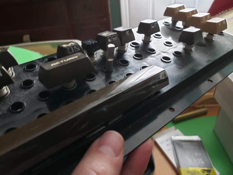
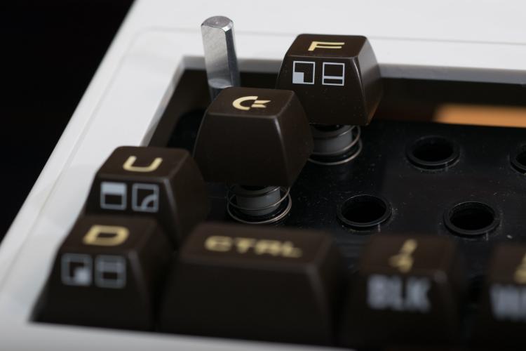
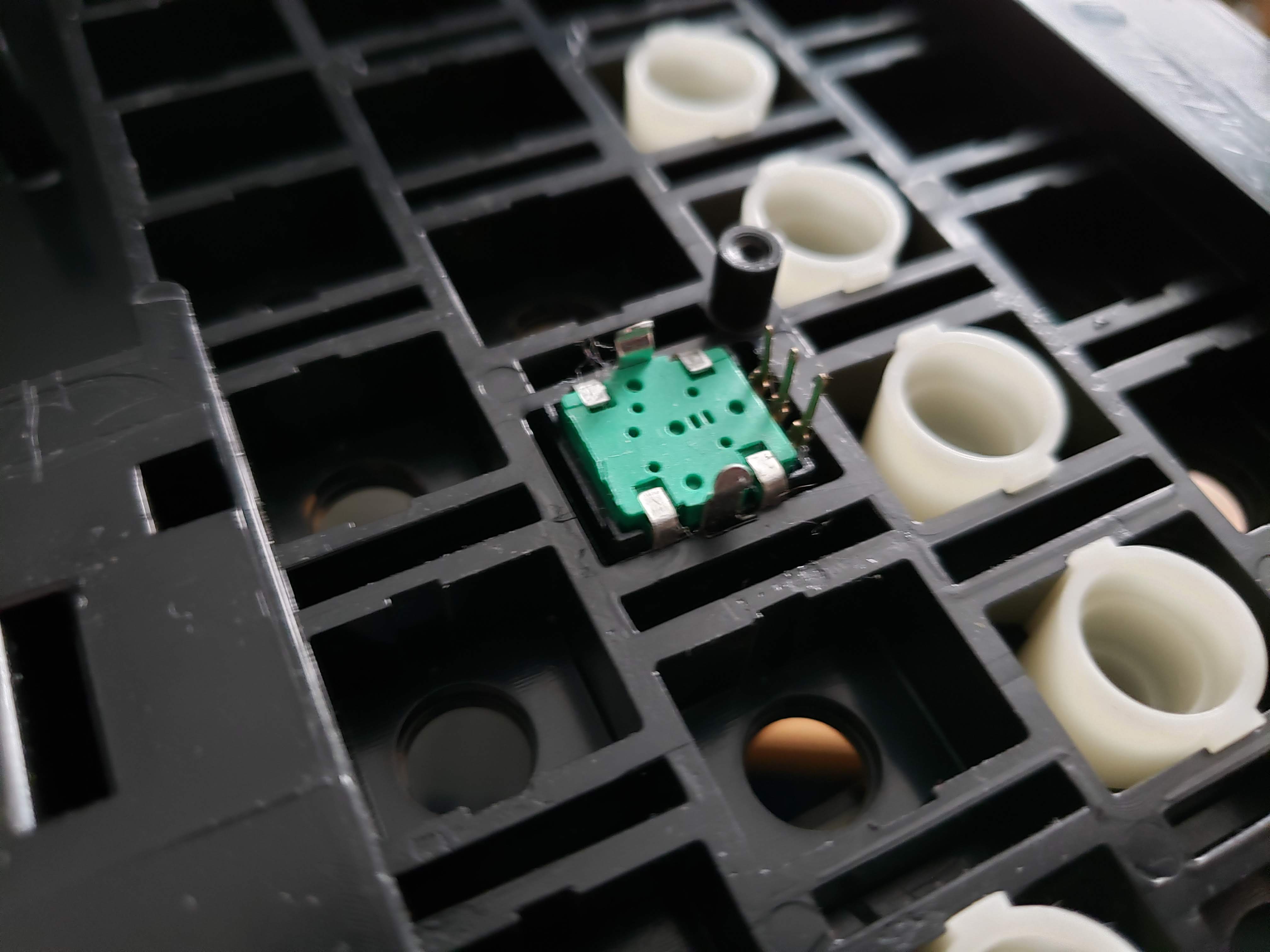
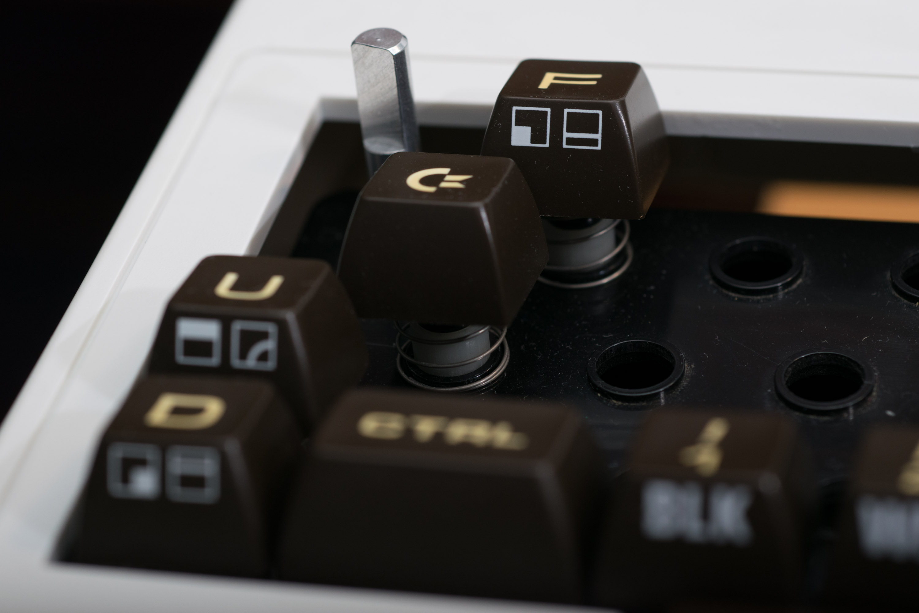
I'm lousy at drawing, but i took some photos to illustrate what I'm doing.
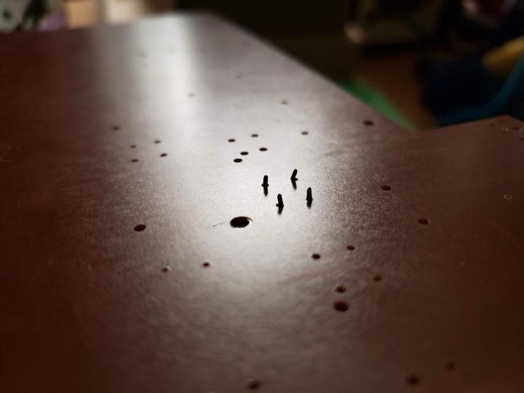
The knobs I got wedge perfectly into the cavities for the keyboard switches on the frame. Those leads will attached to wires between the PCB and the frame and come out a hole somewhere. The switches mount into the board using holes I've drilled. In one of the attached pics you can see the leads sticking through.
My skills using a Drimel drill press have proved less than ideal when it came top lining up the spinning bit with the mark for the hole and so some of the drilled holes have been off by a few mm. I feel bad wasting this keyboard PCB and in hindsight I would have gone straight to creating a board like I'm going to do now (I was less "woke" to retro computer preservation than I am now).


-
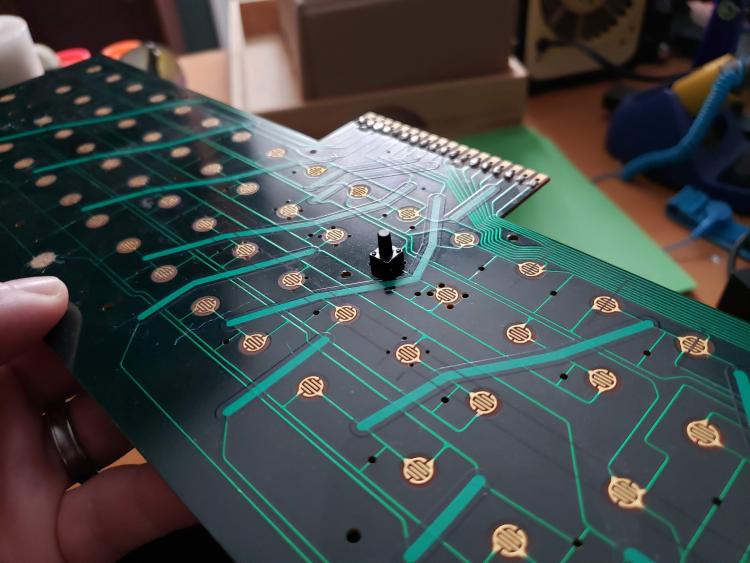
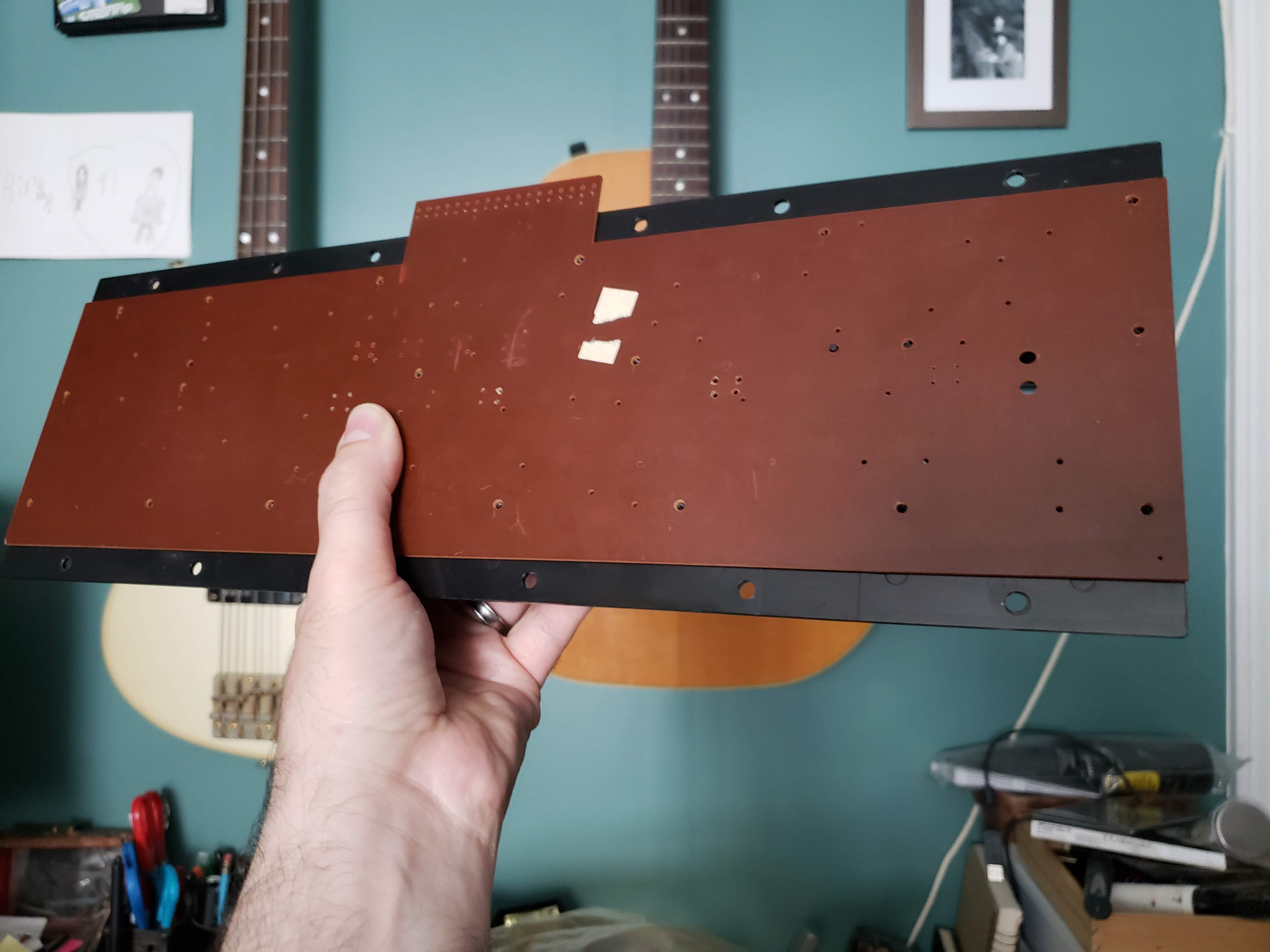
My MIDIbox SID project is using a C64/VIC-20 keyboard as its control surface. The encoders and switches were to be mounted to the PCB that attaches to the keyboard frame (with wires directly attached the the component leads instead of using the PCB's own traces) but I've decided that's a bad idea since I'll have to go through extra steps to make sure none of the preexisting traces on the board short anything.
My new plan is to get some board like material similar in density and thickness to the original keyboard PCB, cut it to size, and use it instead. I was thinking of MDF because it seems it can match the requirements of being thin yet sturdy, but I wasn't sure if this was a bad idea, like if there might be moisture in MDF that could cause shorts. So I thought I'd ask you folks who are more seasoned when it comes to materials and electricity.
Would MDF be a bad idea and if so, what would be a good alternative?
-
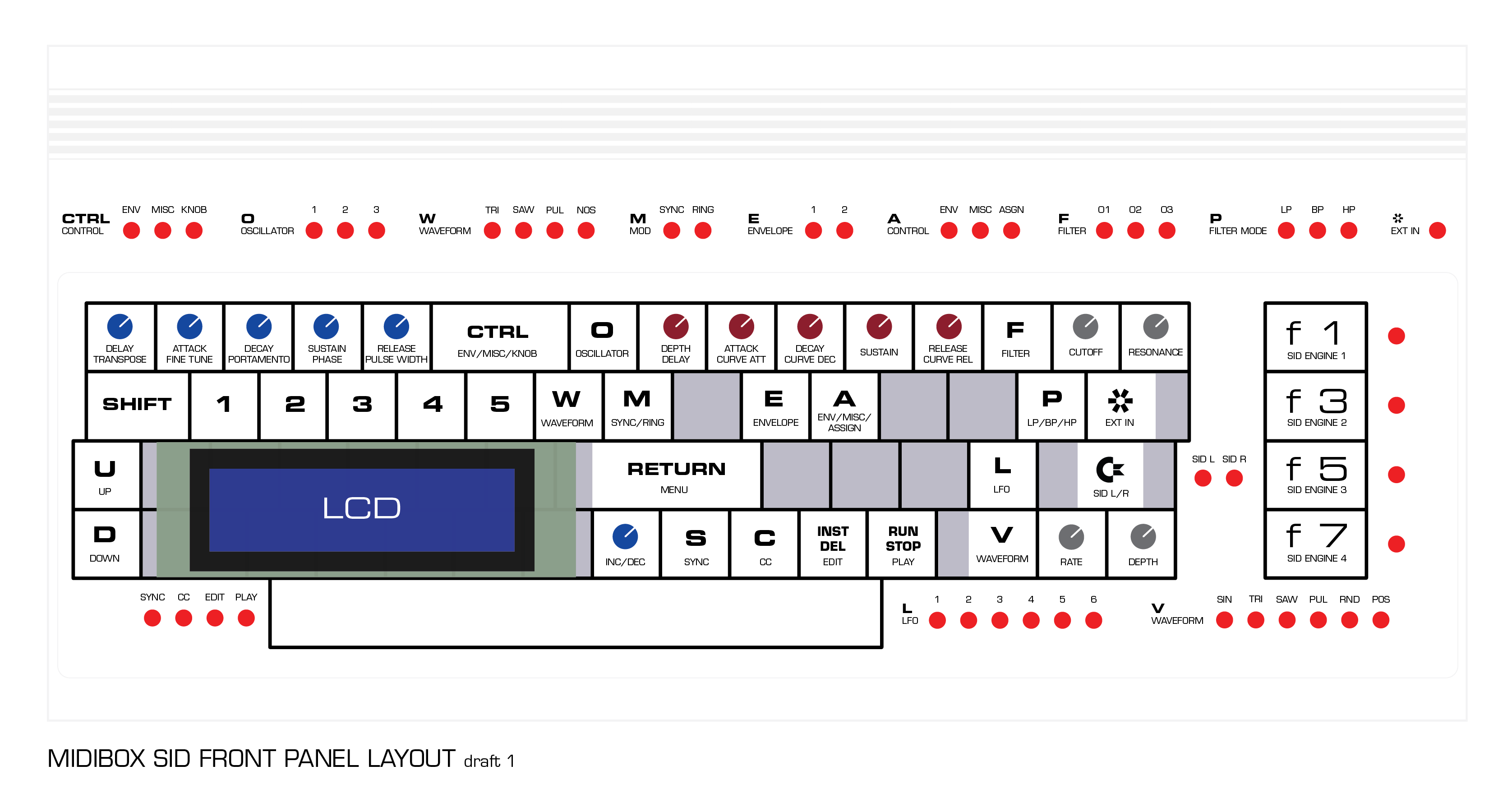
My MIDIBOX SID build is using the MB-6582 main board and a custom control surface. I'm building it inside a VIC-20 case and the control surface is built on a modified keyboard using the keys as buttons. The encoders I got push up through the holes in the keyboard tray. Due to a lack of room I'm not including the matrix. LEDs are placed around the keyboard area and my attached layout shows where I'm thinking of putting them.
I went through a bunch of different layout ideas and ultimately went with whats attached. I tried to keep knobs near the edges so i can put labels right next to them. My goal is to have the chosen keycaps represent the button functions, but I'm limited by the fact that I only have a single keycap set. I'm using the old PET style keys so its hard to get extras without paying an arm and leg. Hence I'd love to have two CTRL keys, but I only have one so I'm using A for Osc knobs ENV/MISC/ASSIGN selector.
While I think I tried to place everything as optimally as possible, I lack the experience of using these devices so I thought I'd see if any of you seasoned MIDIBOXers might have any thoughts, suggestions, or see any obvious pitfalls I might be missing with what I choose to do.
For anyone interested, I'm documenting my progress on a blog on my website: http://www.fallenturtle.com/c64blog
Thanks!

-
Has anyone try using dry transfer (letraset) letters onto a surface like the Commodore 64/VIC case?
-
I already own a ptouch and with clear tape even, but I think it will have the same issue of looking like a sticker. The laser etch transparent panel might be interesting, depending on its height. Thanks for the link.
I didn't realize until I did more research that they make rub offs that can be printed in a laser print, so I'm also considering that since ultimately what I'd like is to have the lettering directly on the case surface and with no shiny transparent margin around them which I think is what I might get with the water transfer technique.
-
I'm building my synth inside a Commodore VIC-20 case. The LEDs will be poking out of the surface so I'm trying to figure out the best way to apply labels to the case surface. One method I'm considering is using water slide decals which are popular with people who do models and custom guitar gear.
The pack of this special paper is $20 so I'm hesitant to buy some if its going fall off or look like crap. Has anyone had any experience trying to use these type of decals on a surface like the commodore cases? My concerns are: 1) while the case is mostly flat, its got a little texture, so I'm wondering if that will lead to the decals falling off. 2) If the case is matte and I'm not planning to apply a clear coat to the top, will the edges of the decals be really obvious and look bad?
I'm also open to suggestions on better ways to apply the labels.
-
I revised my sketches.
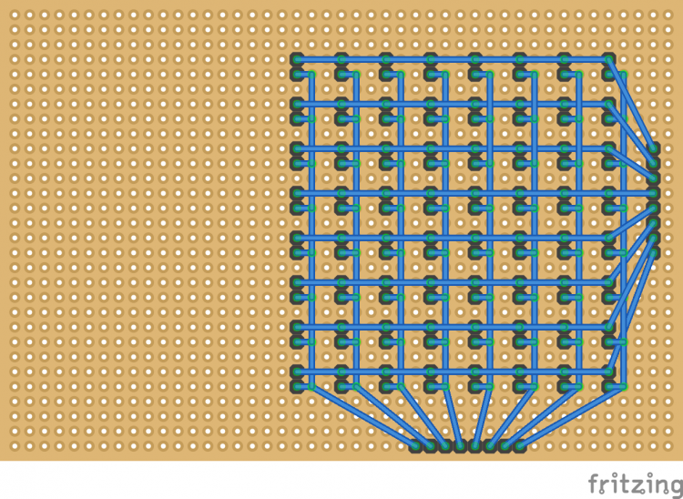
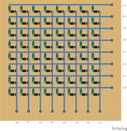
DIN:
DOUT:
-
I'm still working out how I'm arranging the front panel. It's based on a C64* keyboard with the encoders and switches being on the keyboard grid and the LEDs around it coming out of the C64* case surface. See image. Because of this I think none of possible arrangements will work for or against direct wiring vs matrix wiring. I think I'd rather deal with wiring 2 matrices then buy more DIN and DOUT boards and they required components for them (though I do have one DIN module completed from my since abandoned modular MIDIBox SID.
*Actually its a VIC-20 keyboard and case, but I'm pretending is from a C64.
-
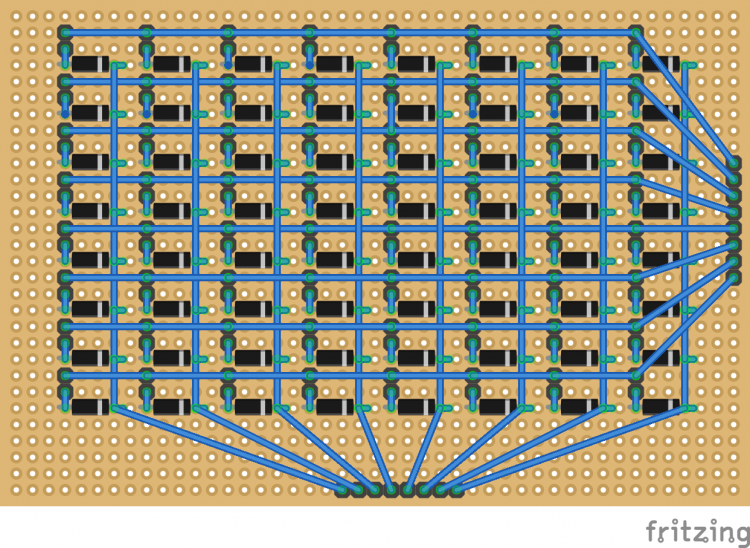
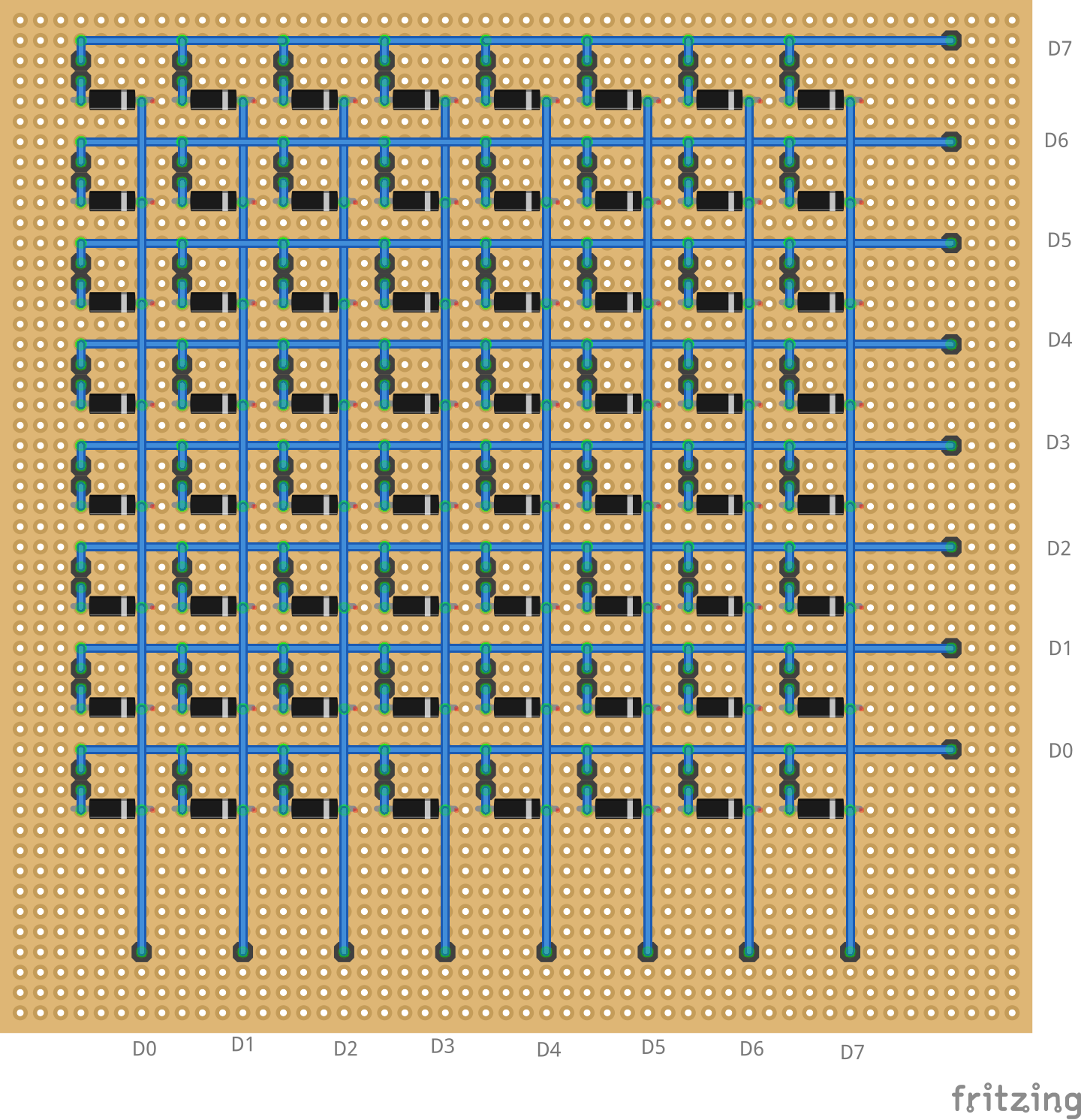
Those are pin headers I'm using for going to the switches and the black horizontal things are the diodes.
-
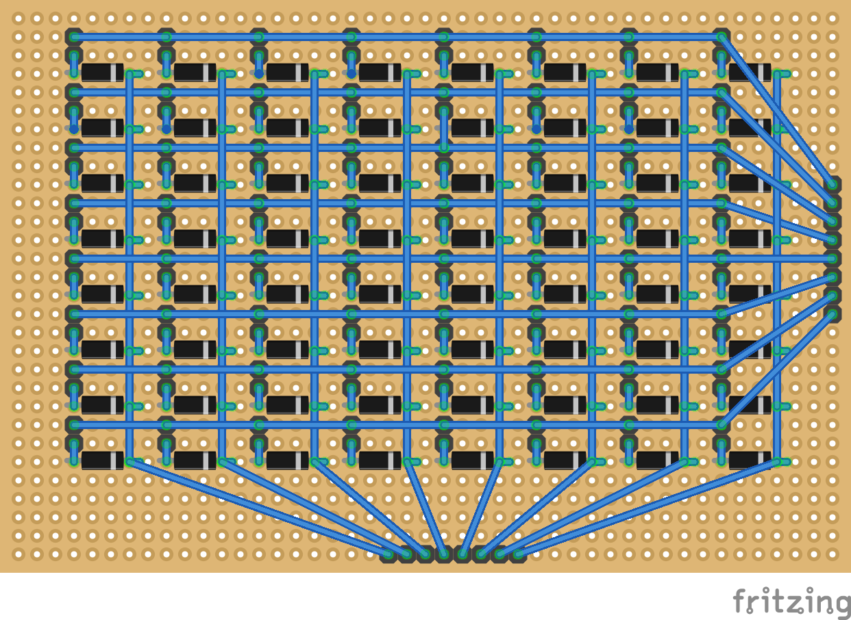
I'll go ahead and add the sinks.
I downloading Fritzing to try to mock up the matrix so to get a better visual idea of what I'm doing. Does this mock look like I get the idea? This is for the DIN matrix.
-
Just now, latigid on said:
Yes, or connect the switch to JD8 and the diode to JD5
Just follow these:
http://www.midibox.org/dokuwiki/lib/exe/fetch.php?media=mb-6582:mb-6582_cs_dout_wiring.pdf
http://www.midibox.org/dokuwiki/lib/exe/fetch.php?media=mb-6582:mb-6582_cs_din_wiring.pdfYou will soon see why we normally use PCBs for matrix routing :)
It is possible to do this and I recommend it in the absence of a front panel PCB. You will need one DIN pin for each switch, with the other pin wired to 0V (ground). No diode is required. For LEDs do the same: you need one DOUT pin + resistor for every LED. If you are completing a comparable control surface to the MB-6582, you'll have to expand the SRIO chain, labelled as J8 and J9 just up from the bottom-left of the Base PCB. and below the J8/9_Core4 header. You can either use DINX4/DOUTX4 modules or wire the chips/resistors/headers etc. onto your stripboard.
If I'm following you correctly it sounds like its easier to create matrix routing on a printed stripboard than direct wire each LED/switch. I was hoping I could just use the DIN and DOUTs that are on the MB-6582 base PCB.
I didn't get the BC547s for T2-T9 because I didn't think I needed them if I'm not using the Mod Matrix, but if I AM using JD8, then does that mean I need them after all?
-
Just now, latigid on said:
A few corrections:
Diodes are essential when the switches are scanned in a matrix, otherwise multiple switches would "activate" at the same time. Notice the cathodes of the regular LEDs and the diodes of the switches connect to the sinks on JD8. The anode sides of the switch diodes (drawn as the floating part of the switch connection) are scanned in on JD5 which will find their way to a 165 shift register. As the "strobe" pulses the transistor bases, the collectors allow conduction through JD8. The DIN pin senses this as pulling the input low and registers a button press. The MCU "knows" what button was pressed by considering what strobe pulse was active at the time. In effect, the current sinks are providing "ground" in a multiplexed fashion.
Okay, so I will need to buy some 1N4148 diodes? The official control surface PCB is some what of a maze for me... do I put a diode between each switch/LED and JD8?
-
Thanks Peter,
That does help, though I'm still a little bit confused and I think it might be related to how I literally wire this up. I guess I was initially thinking I'd run a wire from an LED, LFO1 LED for example, lead to D4 and then another wire from the other LED lead to ground. Am I to understand correctly that I'll want to recreate those matrices shown in the PDFs on a piece of strip board and wire everything through that?
Would I want to remove the "16 +" from the DOUT table in the asm file? Actually I realize my understanding of how the PCB connections translate to the asm file are off. For example for LFO1 LED it says:
DOUT_ENTRY TMP4, 0, 16+3, 3 ; LFO1 LED
Which I previously would have thought was JD3 Pin D3, but its actually JD7 and Pin D4 according to the wiring chart.
Sorry for being such a dunce!
-
I'm building a MB-6582 based synth, but instead of using the official control surface PCB, I'm making my own surface. It will have all the same buttons, LEDs, and encoders that the official control surface has with the exception of the matrix. So I'm trying to learn how to build out the CS based on the MB-6582 CS but subtracting what I don't need, which has led me to some confusion because I'm a noob:
- I think I might be getting my matrices confused. Is there only one matrix, or is there the matrix has in the grid of leds and buttons on the control surface and also matrix, as-in a way of connecting inputs and outputs?
- If I'm not doing the LED matrix, do I need any diodes for the other parts of the control surface or can I just wire everything directing to the DIN/DOUT along the bottom of the MB-6582?
- Are mb-6582_cs_din_wiring.pdf and mb-6582_cs_dout_wiring.pdf found in the Control Surface Wiring section of http://www.midibox.org/dokuwiki/doku.php?id=wilba_mb_6582 exclusive to the LED/button matrix?
- Is each JD header on the base PCB (JD1, JD2, JD3) equivalent to a shift register? Would the JD number correspond to the shift register number used in the asm file?
- If I wanted to keep the same pin assignments that the MB-6582 asm file uses, but without the LED matrix, would I just remove the 16+ part of the shift register assignment?
- How do I deal with ground? Do I just chain the ground pins of the components per shift register and connect them to the ground pads next in between the the JD headers?
Thanks.
-
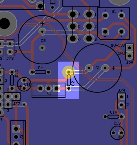
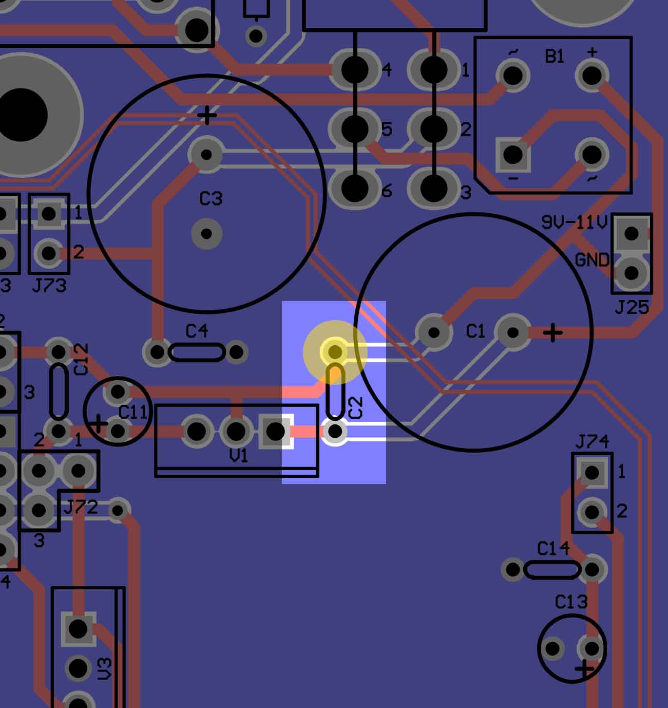
It is, in fact, tantalum. Would the marked hole in the attached image be positive (the upper or right of C2)?
Edit: I have to place an order for some parts anyway, a ceramic and non-polar cap is 30 cents, might just do that... its rated to 50V as well instead of the TAP334K035SCS' 35V. I'm not sure why I bought such an expensive cap.
-
I accidentally ordered a polarized capacitor for the power supply section of the MB-6582 that goes in C2. If I place it the correct direction will I still be able to use it here or do I need to get a non-polarized version?
-
So I've ultimately concluded that its not possible to put a MB-6582 in a C64C case while retaining the keyboard (with its PCB attached) because there's not enough vertical space at the front to fit the MB-6582's components. So I'm going to install the synth in a re-labled VIC-20 case. Since I now have an extra 64C case and a keyboard I'm also going to put together a Raspberry Pi "retro" gaming system. :)
If anyone is interested, I'm blogging/documenting my progress: http://fallenturtle.com/c64blog
-
Do I need to add caps C1, C2, C4, C11 and C12? I'm doing a mixed SID setup. I see everyone has them in the photos in the this thread. The build guide said they were optional and for PSU Options A and B so I might have foolishly not bought them thinking they weren't needed.
Edit:
Never mind, I ended up ordering those pieces just to be safe. If they are required, I'd advocate they be added to the OP -
9 hours ago, latigid on said:
Pin 3 has no isolation so is part of the ground (0V) plane.
Whew, thank goodness.
-
http://www.midibox.org/dokuwiki/lib/exe/fetch.php?media=mb-6582:mb-6582_base_pcb_r2_color.pdf
I screwed up when soldering between two pins for the header at J71. Specifically at pin 3 and the ground pin right below it. Its near the upper right of the board to the right top of the furthest right SID IC. The area between them got worn down or scratched when I was trying to fix an accidental solder contact between them.
I can't tell from the board diagram if pin 3 is grounded, but now when I try to test pin 3 and the ground pin below it with my continuity tester they are connected. I'm really hoping they're supposed to be and I didn't just royally screw myself. :(
-
On 9/7/2017 at 3:37 AM, eptheca said:
Nope :(
I have had the same type of outrage here on this forum re-using old Sinclair computer cases.
arti492 wrote : You destroyed the ZX Spectrum, you should burn in hell
They're wrong, that's beautifully and tastefully done.
-
27 minutes ago, Hawkeye said:
Offtopic and just a remark: sometimes i got roasted when posting MBSID songs to C64 centric groups. People were claiming, that the MB6582 must be pure evil and surely has gathered lots of bad karma, because it contains SIDS from C64s, that are no more (it did not matter that i "harvested" only from otherwise dead machines and also wrote that). Posting pictures like the one above on a commodore group page is certain to cause extreme public outrage, so be prepared for that, if you want to create a similar case! :-)
Many greets,
PeterGood to know... I assume midibox.org is safe enough. :)


MDF board to mount control suface compontents... bad idea?
in Design Concepts
Posted
I think my accuracy issues might be more related to the drill press itself. There's definitely some play with the arm that moves the drill down and maybe there's a way I can tighten it, I'll have to look, but probably not, its pretty cheap. I assume the slide won't help with that?