

ChinMuzik
-
Posts
105 -
Joined
-
Last visited
-
Days Won
1
Content Type
Profiles
Forums
Blogs
Gallery
Posts posted by ChinMuzik
-
-
On 9/20/2017 at 4:23 AM, Smithy said:
It's not Java Script, it's a Java executable.
Just download and install Java on your machine and run the .jar file.
Make sure the midi in and midi out of the MIDIbox SID is connected properly otherwise you won't be able to open the patch editor interface.
Right, but in the link you posted there's no .jar files just CLASS files.
-
On 12/20/2016 at 2:18 PM, Smithy said:
Your best bet is using Rutgers editor.How do I even use this?? I've downloaded it.....does it need to be compiled? Never ran a Java script this way.
-
On 6/20/2017 at 11:18 AM, jaytee said:
I bit the bullet and bought my Mb6582 display from Crystalfontz. It was a little pricy, but with how much variance in quality there is between LCDs, I figured it was worth it to get something nice.
I wish but they don't have a white character on black backing. I kind of need it.
-
21 hours ago, Altitude said:
Mouser
Searching 20x4 LCDs on Mouser give seriously anemic results. I think none listed were the Kyocera ones also.
-
Does anybody know where to get these? I'm in kind of a scramble to get a 20x4 display for my MB6582 and need an LCD. I dont want to buy the cheap ones from Hong Kong unless absolutely necessary
-
Yea, I got it all working. Reading the walkthrough, I was expecting some kind d of visual feedback in MIOS Studio when the bootloader is detected. Apparently there is none.
-
I'm gonna give this a go again.
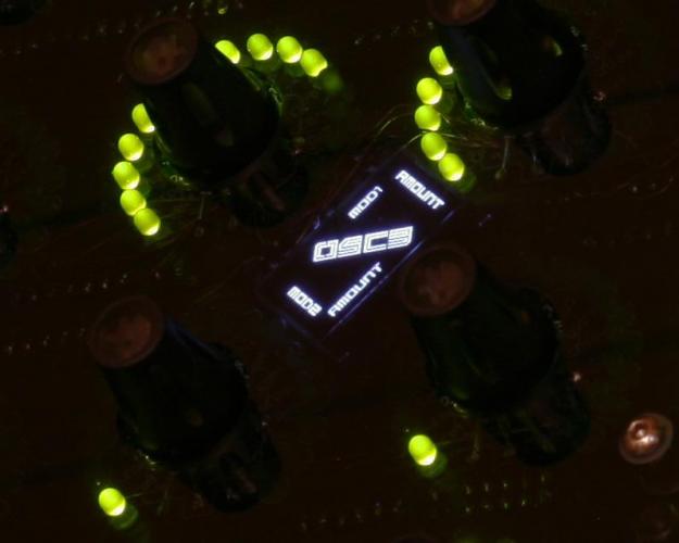
The VFD looks so good
-
3 hours ago, latigid on said:
Of course, I asked incessantly if they could add switches, but because of the design that isn't possible. The workaround is to use individual metal touch sensors, which is a bit different but is quite easy to get used to I think.
I might be alone on this, but I actually prefer the capacitive touch knobs over push encoders
-
I have a reflow over, so SMD is not really a problem.
Scribble strips...Tiny character OLEDl like this.
Except with a smaller one that will be under each control. So I can imagine this would now be the most time intensive part :D....
-
I was browsing Hawkeyes MBProgramma build and was wondering how intensive a project for a similar patch editor would be which would consist of the following.
16 LED ring encoders
8 faders
16 buttons
Each with a dedicated scribble strip which would display the parameters of a synth (which would be saved as a layout in MIOS?)
Maybe even highlight the relative controls, similar to the Kiwi Patch Editor.
Thoughts?
-
Just had a weird revelation.
After burning the bootloader, even though MIOS studio doesn't send any message that the bootloader is detected, it clearly sees the bootloader as it will allow the uploading of MIOS and the LCD driver.
Is this a know quirk of MIOS studio or am I just overlooking some obvious indication that the bootloader is being detected?
-
Not sure what I'm doing wrong but my VFD display is giving some garbage output.
I've done the following in order.
- soldered the SMT Bridges and checked for continuity
- uploaded device_id_00_lcd7.hex
- uploaded setup_mb6582.hex
Powered up, I'm getting this.
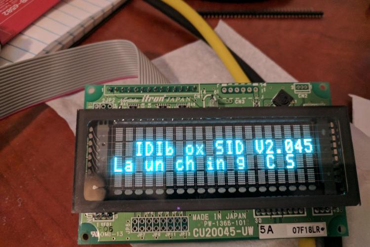
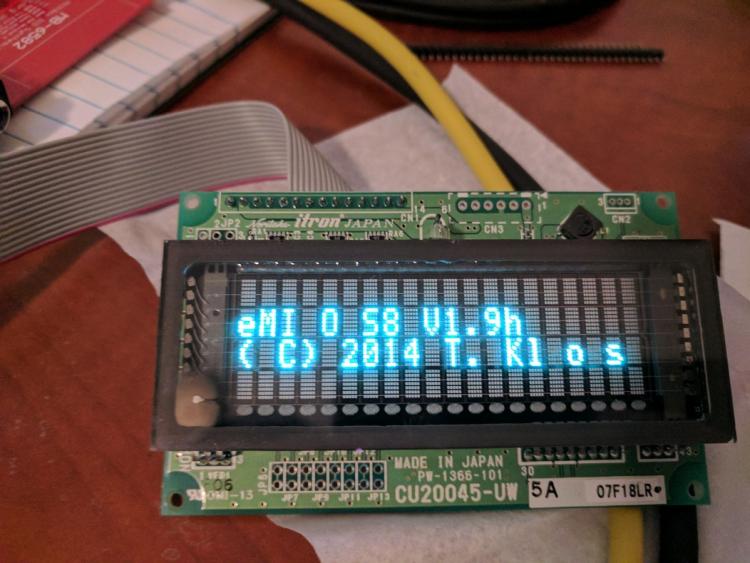
-
So I ended up exporting the .hex from the preburned PIC I received from SmashTV and then flashing it to each PIC I received from Mike, then changing each ID with the change_id app. Successful, MIOS sees all 4 cores.
Still would like to know why it was failing to see the PIC after burning the bootloader.
-
So my PICkit2 came in today. I loaded the PIC into the ZIF and the application detected it as the 18f6485 family...
I burned the bootloader hex successfully and verified it successfully. But when stuffing it in the mb6582 base PCB, MIOS Studio still isn't seeing it. But sees the PIC I purchased from Tim with no issue.
Also, when I take the PICs I purchased from Mike back to the PIC programmer, it can no longer verify the program and it cannot be deleted either. It will show deleted but when doing a blank check it will fail.
What are the odds of having 4 bad chips? Could they be counterfeit possibly?
-
-
On 12/29/2010 at 3:20 PM, jojjelito said:
+1oneoneeleven!!!!111
As long as the ST32 outputs the correct timer signals to the 3396's waveform converters we are gold.
Me on this: Stalled for now :(
Back to Xcode.
How bout the 3372 too?? :D
-
I'm curious about this...The encoders are by far the most difficult decision of my build to make.
Do you hear any stepping when sweeping the filter?
-
Yes just kinda blows because I've been waiting almost a month for the PIC programmer. Doc offers the burning as a free service and I specified I needed it. Oh well....At least it's squared away. Building an MB is a long and drawn out project lol
-
Received my PIC from Tim today, popped it in and success...
It was indeed the bootloader not being burned on my PICs.
-
I don't understand why they don't have preassembled JST XH cables with dual female 8-pin sockets.
-
I buy all my resistors, ceramic caps, diodes, some transistors, jacks and sockets from Tayda.
I don't buy pots, IC's and electrolytics and film/mylar caps from them.
I did buy the shift registers for the MB build from them though.
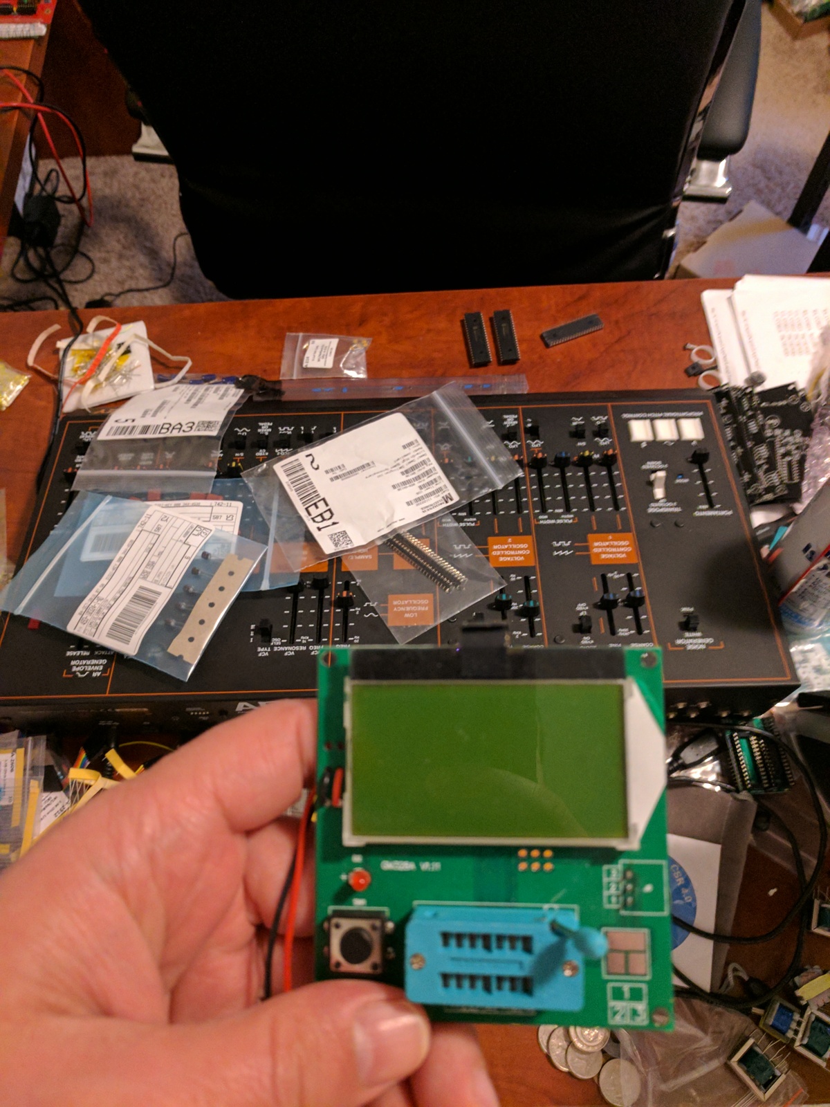
Even the caps and resistors I buy I test with this handy little thing (pictured).
Also: back to the troubleshooting. Reset at the PIC didn't help...and I am pretty sure the 10mhz crystals are parallel cut, I remember someone telling me values that low are almost always parallel cut. One other thing on that, even if it was serial cut..Doesn't the PIC force the crystal to oscillate how it wants?
One more last ditch attempt before I dump the funds on a Pickit2...I didn't check the following (because the test flow considered both I/O to be functional).
- TEST OUT3: Somebody noticed in the forum, that the MIDI Out of his core module didn't work because of an "incompatibility issue" with the bench supply he used and the switching PSU of his PC. The solution was to disconnect the middle pin of J12 (ground line of MIDI Out port)
What is J12 represented as on the mb6582 PCB? I can't seem to locate it.

-
No, no other PICs to test with. I will need to order one for a build I will make soon. So I guess I could order from Tim as it will have MIOS already installed. That would clear things up right away.
I will try the reset at the PIC now
-
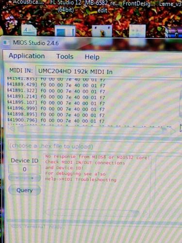
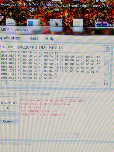
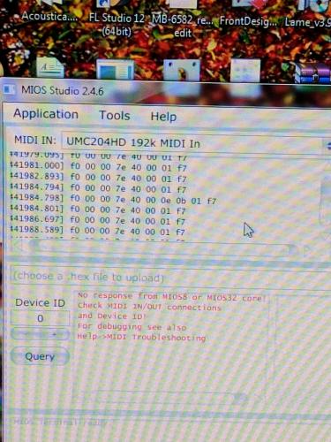
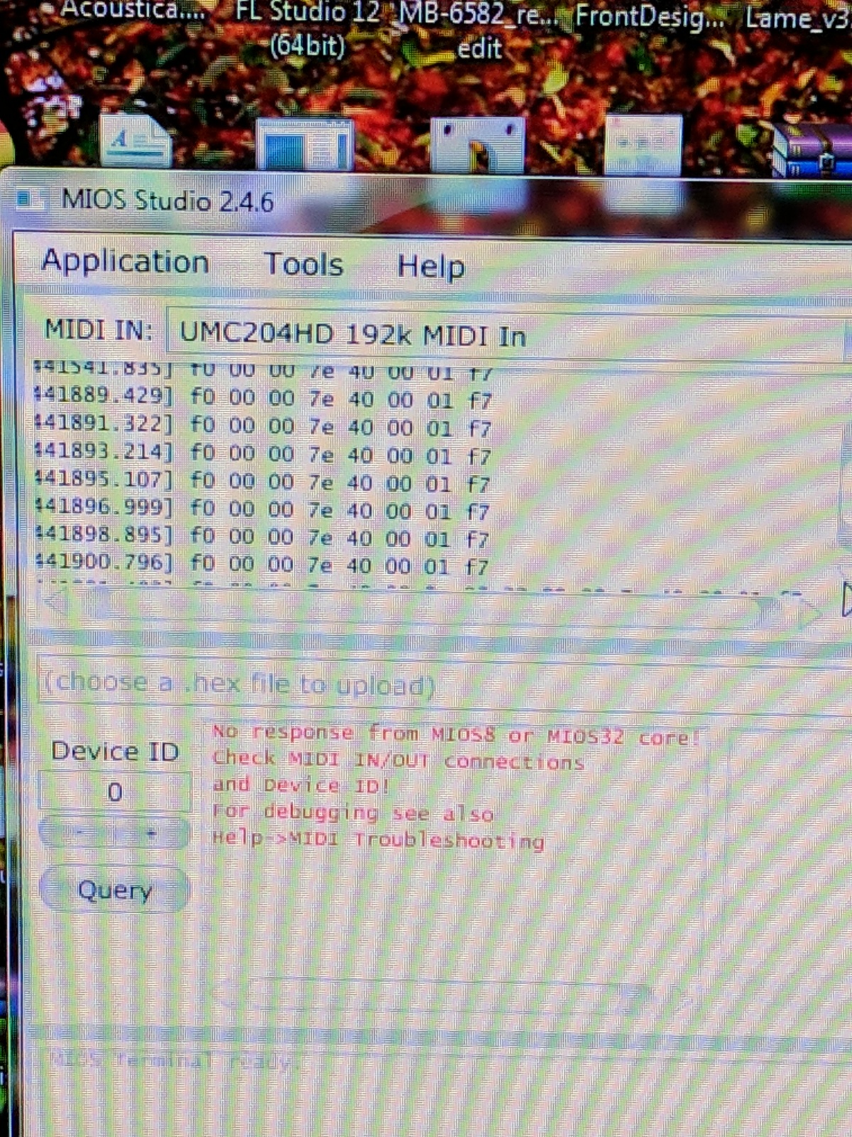
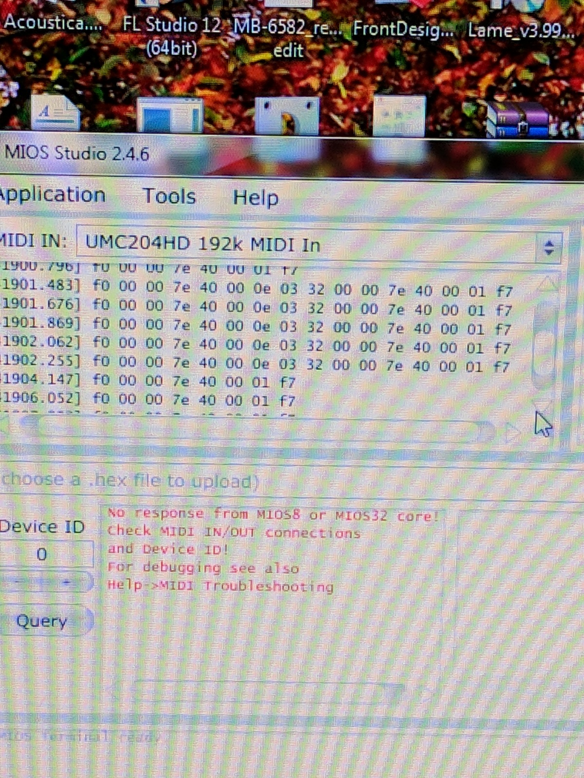
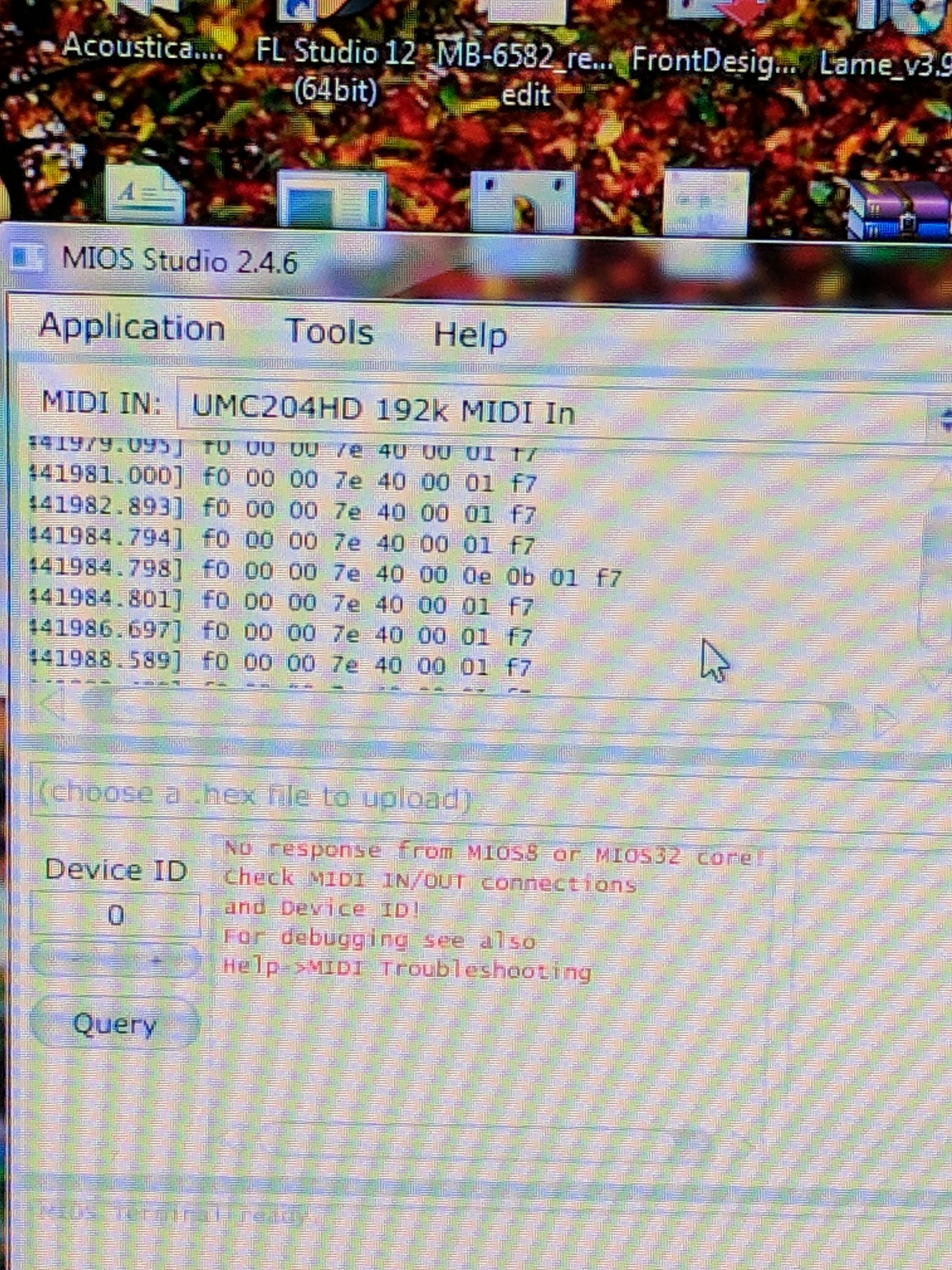
Ok, tried again.
I've attached photo to show exactly what happens.
The first photo show the messages that flood when I turn the PSU on with any 3 of the 4 PIC loaded in any single core.
The second picture shows what happens when I query the same 3 of the 4 PIC's
The third picture shows a different message that will OCCASIONALLY appear when doing a query.
These events are the same in all positions on the PCB and no matter what Device ID is set in MIOS
The 4th PIC generates no messages no matter where it's seated.
-
4 minutes ago, latigid on said:
If you have one "Core" position where one PIC works and another doesn't, maybe it's a problem with those PICs? If you're in Germany, you could send me the PICs and I'd check them for you.
Technically, none of them work. They just "don't work" in different ways lol. Which is why I believe it to not be the PICs..Unless the they weren't burned with the bootloader. But Mike explicitly said they would be.
I'm in the states, it might be more cost effective to get a clone PickIt2. Just that it would suck to buy it and it not be the issue.


[FS] 5x 8580 R5 + 1x 6581 SID chips
in Fleamarket
Posted · Edited by ChinMuzik
Keeping 2
All tested and working. Pulled over the years from working 64/128's. Going 100% software now and all my hardware has to go
$210
Will possibly ship internationally but would prefer not to.