

bemerritt
-
Posts
14 -
Joined
-
Last visited
Content Type
Profiles
Forums
Blogs
Gallery
Posts posted by bemerritt
-
-
Sounds good, thanks for the quick response.
-
Looks great. Anything we can do in anticipation? I assume a core and midi boards can be built up.
-
any news?
-
Someone take this off my hands. Don't have the time dedicated right now and I don't like have unfinished projects lying around. Below are the boards I have and their status (purchased from modular addict)
https://farm5.staticflickr.com/4499/36995031913_bbb12d22a1_b.jpg
MIDIbox DIGITAL OUT (DOUT) PCB MID-DOUTXX-PCB 1 $6.99 - tested and working
MIDIbox Core STM32F4 PCB MID-CORSTM-PCB 1 $9.99 - tested and working
MIDIbox AOUT_NG PCB MID-AOUTNG-PCB 1 $8.99 - still debugging
MIDIbox SEQ V4 PCB MID-SEQV4X-PCB 1 $34.99 - tested and working
MIDIbox MIDI I/O PCB MID-MIDIIO-PCB 1 $6.99 - built, but no midi devices to testBetween the boards, screens, and parts im in it over $400. Looking for $300
-
What about SD card inserted with no CS connected?
-
I did the latter, right to the core with the cable. Actually used jumpers to really make sure i did it right.
-
Just as another data point, I am still troubleshooting an AOUT_NG. However when I do the testaoutpin, i get 0v and 5 volts, which is what MIOS tells me I should get. That is except on one pin that is not flipping, so thats my next step, to trace that back, but that issue should be on the core board, not the AOUT_NG board.
-
As a newcomer, this looks like an awesome update. Any chance the overall height will be slightly smaller that the previous version? The v4 is barely to tall to fit behind a euro panel.
-
I assume the AOUT_NG is hte same. Sounds like just insert the patch cables to the aout module first and it should be fine..
Thanks!
-
Is there any precautions that one should take when connecting the analog outs to a modular setup?
I will eventually add line drivers and most likely a euro panel once I get ahold of some boards, but in the mean time, is there anything special i should do to connect the two. The plan right now is to just connect the pins to a breadboard that has some jacks on it, and connect them all to the ground for that jumper as well.
I noticed a while back that the boards for euro have more to them, but i presume this is for protection of the circuit incase you plug an output in.
Any insight greatly appreciated!
-
Well, that did the trick. Something as simple as mounting it on the front was something I hoped it would be, but is also rather emabarassing! Thanks for providing the second pair of eyes, I had tried way too many things yesterday and it was driving me crazy!
Now the fun begins to get all of the different modules talking to eachother begins.
-
Any chance these are still available, or able to order and ship one to the US?
-
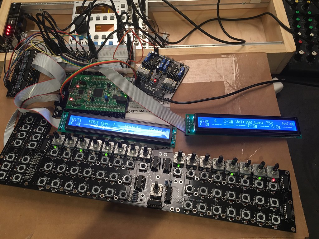
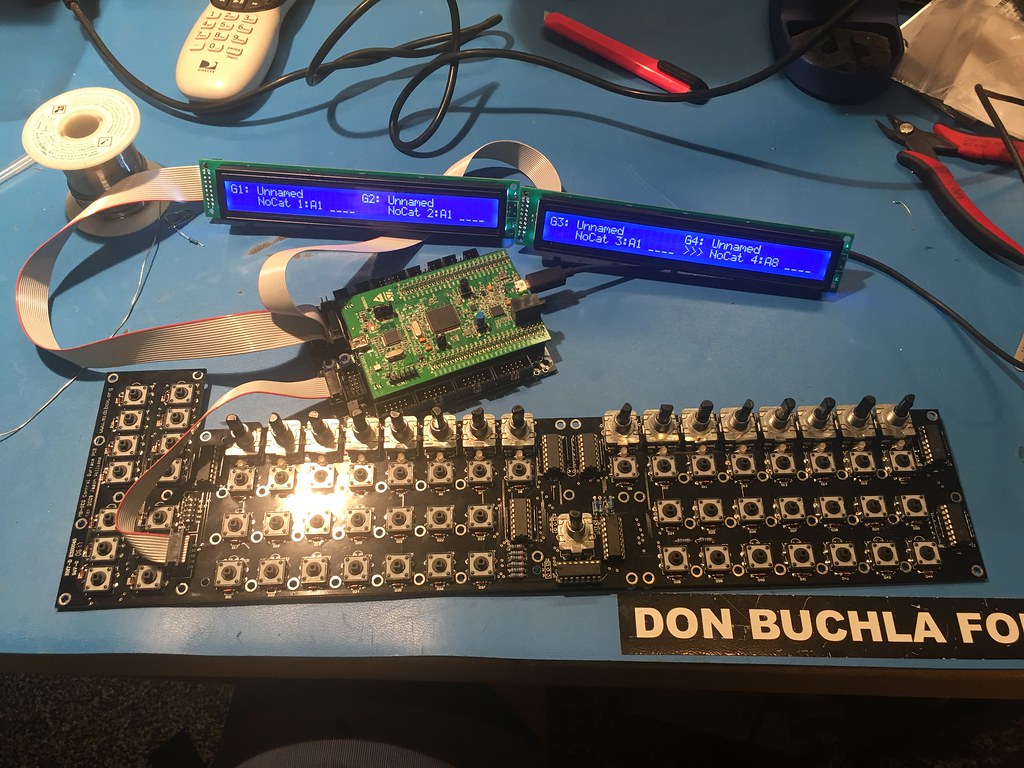
So over the weekend I soldered up all of my boards (core, cs, Midi I/O, DOUT, AOUT NG), and am having trouble connecting the CS. I have spent hours reading old topics on the matter, but could use some help.
First step, SD card is formatted and I have what I think is the right file in the right place.
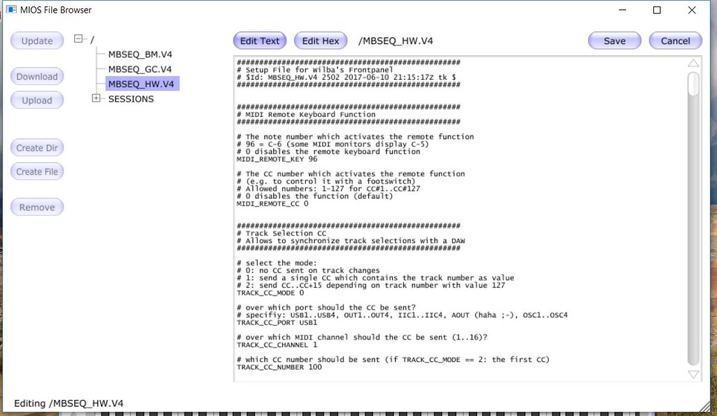
Connected the boards and get this
I used jumpers just to make sure I had the correct pins connected. To J1 i get know response, on J2 i can get all sorts of response by touching the solder pands on the bottom of the baord
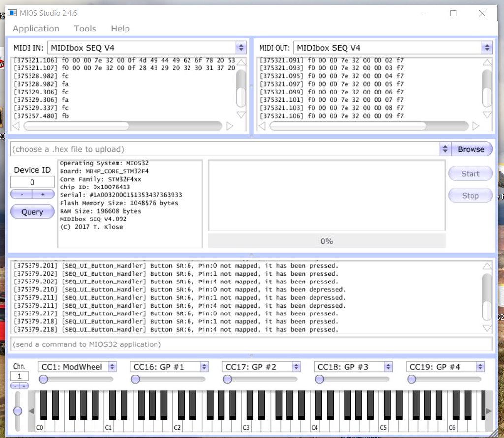
While connected in this fashion, i get this in MIOS
Which makes it looks like buttons are being pressed. Suggesting I have shorts. Looked at every joint under a microscope (I'm used to doing SMT work), and nothing there.
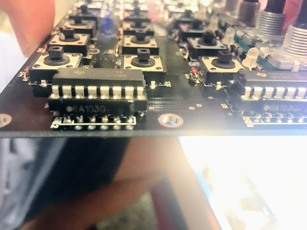
Previous threads had called the resistor networks into question. Here is what i used, all showing 5 volts on the common pin.
I also left these jumpers empty, which shouldn't be a problem
Some other notes
- Not all leds are soldered, i just did the 16 bi-colored ones
- I defintiely connected the boards backwards, could i have fried my ICs on the CS? (have some new ones on order)
So, any ideas? Anything to help troubleshoot would be awesome. Thanks!
edit: is there an issue with having more than one picture in a post?
MIDIbox SEQ new frontpanel idea
in MIDIbox SEQ
Posted · Edited by bemerritt
any idea when the pcbs will be available? Also, thanks for all the hard work! Excited to see it completed.