nebula
-
Posts
943 -
Joined
-
Last visited
-
Days Won
4
Content Type
Profiles
Forums
Blogs
Gallery
Everything posted by nebula
-
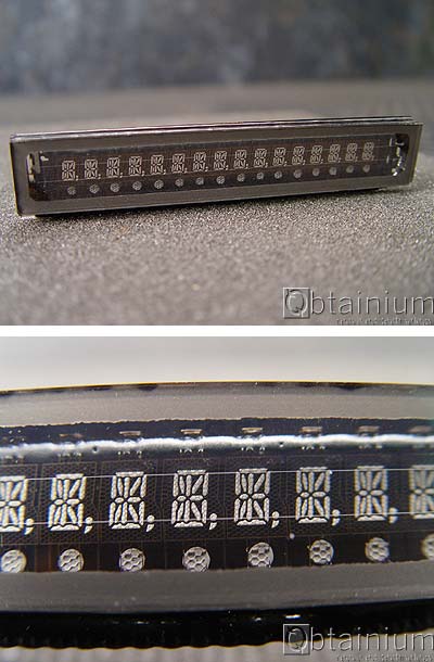
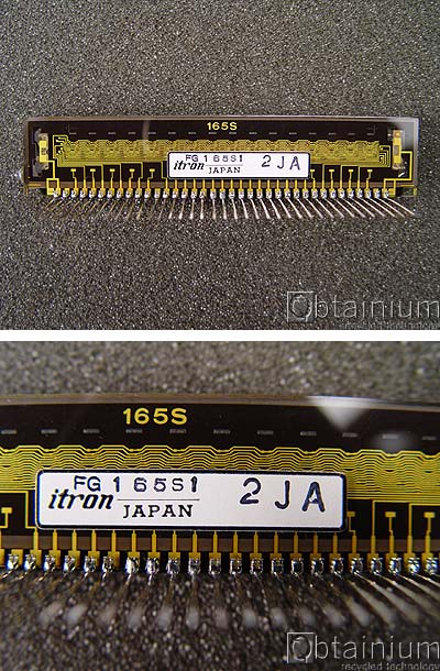
I would love to know how these work: http://cgi.ebay.com/ws/eBayISAPI.dll?ViewItem&item=140303558420 (Model FG165S1) - these look like the display in the Roland JX-8P. I know they are old-school, but I really like the look of them. But all those pins ... judging from the way the traces look on the back, the segments would be lit with a common anode or cathode for each character, along with a separate lead for each segment. Then you've got a couple of extra pins on each end that appear to energize the entire display, requiring a high voltage (presumably this is the "grid"?) Can anybody offer a quick primer on the electrical properties of VFD?
-
Phil, that's a sweet looking button. I got the data on it and I see you can get the coloured ones with an LED in it for a pretty good price. Have you tried the illuminated ones? Got any pics of a lit up one?
-
I don't know if this is old news, but it's AWESOME
-
This would absolutely be possible. AFAIK the existing MB-SID firmware provides no functionality for CV inputs, but it can output lots of stuff via AOUT. You can route audio through the SID inputs with no additional hardware. The MB-6582 puts the entire "standard" MIDIbox SID components on one board, yet the Cores still have full connectivity for other MBHP modules. AOUT / AOUT_NG could connect to the MB-6582 core using a 5-conductor ribbon, and although I haven't tried it myself, I believe this would work through the DB25 accessory connector on the MB-6582 rear panel. MB-6582 is less practical if you want deviate from Wilba's panel, as it would involve modifying the MB-6582 matrix code and/or adding additional DINs/DOUTs... in which case you probably would be as well off to go with the traditional, discrete module-based "spaghetti" approach.
-
Thanks - I misread that ... but what does "offcause" mean?
-
Hi, welcome! Who doesn't? People who want to use custom enclosures, people who want to tinker, people who already have the spare boards, people who want to make their own boards at home... It's all on the board. Rotary encoders send a signal to the CORE, via a DIN, every time the encoder is rotated left or right, telling the firmware to increment or decrement a value. A rotary encoder "with switch" can also be pressed. Many car stereo tuning or volume controls are like this (turn left or right to change the station, and press to see the time). The MIDIbox SID firmware does not make use of encoders with built-in switches. So you could get them if you want, but the added swtich would add no extra function, and the additional pins for the switch might get in the way. Of course, being an open-source platform, you would be free to revise the firmware to add functionality to the switches - but then, you might want the modules as individual boards, because you'd need to add extra DINs to read the switches. Time. Lots of it. Beer helps too.
-
My apologies if this has been implemented already, since I have not built an MB808, but I just had a thought: A good way to implement this would be to hold down a "program change" button, which toggles the display and turn the encoder. While turning the encoder the program change appears on the LED display, but it is not sent until you release the button. Maybe then the display could quickly blink to indicate it was sent, then switch back to BPM. Reason: some drum machines and grooveboxes load big banks of samples on every program change, so you don't want a program change sent every time the encoder "clicks". Also: an additional LED would not be required, because you already know you're in "program change" view, since you're holding down a button.
-
A friend of mine was really happy with an Alesis io2, but I don't know the specs of it. It is rock-solid with his Windows box, and inexpensive.
-
Me too. You've got me wanting to reproduce the drum voice circuits from the schematics you provided! :)
-
Bugfight's been busy with them! http://www.midibox.org/forum/index.php/topic,10004.0.html
-
From nothing to 2 working SIDs?? (mono6581 and MB6582)
nebula replied to jooks's topic in MIDIbox SID
I don't know if it's precisely related to your problem but option "B" has no 5V regulator because the 5V output from the C64 is regulated already. http://www.midibox.org/dokuwiki/doku.php?id=wilba_mb_6582_base_pcb_construction_guide&s[]=6582 -
I used to have one, but it was stolen .... but what a great sounding machine - much nicer IMHO than a TR-606. The best option for a box like this is often your own linear regulated power supply. The schematics you attached don't actually show what's happening at the power input, so if it has no regulator, consider spending under 10 bucks on some protoboard, a regulator, a rectifier, and a couple of capacitors. If there's already a decent power supply on board, any ol' adaptor should do the job. I think the spec calls for a Boss PSA, which is just a 9VDC adapter with centre negative.
-
The "Photobooth" application takes mirrored pics by default AFAIK. First: make sure you used the 7812 regulator, not the 7809. If you remove the power, take out all the ICs, and then reapply power and test the voltages at the ICs, what do you get?
-
From nothing to 2 working SIDs?? (mono6581 and MB6582)
nebula replied to jooks's topic in MIDIbox SID
A couple of things... The front panel: are those the new Omron B3W pushbutton tactile switches? They look nice. And I kinda like the way the creme-coloured front panel looks with the wood cheeks. To my eyes it's classier than black. Solder joints: first, a round solder joint is not necessarily an indication of a bad solder joint. It really just means there's too much solder, and it's impossible to visibly inspect. It's probably fine. The real thing to watch for is bumpy or grey solder joints. The thing is, a joint which would have been bumpy or grey can look nice and shiny if you use too much solder. Getting that exact amount consistently is really a technique that takes some time to perfect, but your work looks excellent. So don't sweat it. As far as soldering MIDI connectors - if you have a temperature-controlled soldering station, and it includes a variable temperature, you really should be ramping up the heat for MIDI jacks. Take a look at how thick and long those terminals are as they go up from the board into the connector. Also take a look at the huge holes and pads they fit into. All of that metal acts as a big heat sink, wicking heat away from where you're trying to solder. Any time you get into the chunky metal, like jacks, heavy-gauge diode/rectifier/regulator leads, or wires you're trying to solder directly to a board, you probably want more heat than you would normally use for resistors or DIP sockets. ... And you are absolutely right: DIY music electronics is a really great way to eat up your time. It is extremely rewarding, but sometimes you need to step away from it all and make some music, with or without your homebrew toys! -
Gotta be JB-weld.
-
That's a strange machine to have a hum issue. Does it hum on battery power?
-
Still considering panel designs for my rackmount MBCV. The CV/gates will be on the back, and I can't decide whether it's more logical to go with: CV1, GATE1, CV2, GATE2, CV3, GATE3, etc... or CV1, CV2, CV3, CV4, etc ... followed by GATE1, GATE2, GATE3 ... (as you have it) Looking at your panel just reminded me that I haven't made up my mind yet! :(
-
You can't use a hacksaw to convert a TL074 into two TL072's.
-
I'm thinking about diving into midbox, Gurus advise
nebula replied to Technosoul's topic in MIDIbox SID
I don't get it ... ? -
Dude ... Last week you wanted to solder stuff from the wrong side of the board, and now you want to cut and splice ribbon cables. Both are possible, but there comes a point where "best practice" must dictate. As a repair bench technician, I have to tell you I've never found a reason to do either. There are times when shortcuts are tempting, but it always comes back to haunt you. It can take a few extra minutes to do the job right, but later, when the device fails for some reason, your weird little shortcut will be one less potential point of failure. Honestly, if I ever had to cut a ribbon cable, I would most certainly always replace the entire cable.
-
Just purchased a load of secondhand MIDIbox SID boards
nebula replied to LektroiD's topic in MIDIbox SID
Hi Rich, I looked at the datasheet. Looks like this display is MIDIbox/MIOS compatible, however the MB-SID application requires at least a 20x2 LCD. To answer your question, it is LCD type "0". 99% of all MIDIbox projects are built with this type. You should be able to connect this LCD to your core module, and as long as MIOS is on the microcontroller, you will see a "READY." message. -
Desoldering / resoldering an IC with no access to underside.
nebula replied to Futureman's topic in Miscellaneous
If the board has plated through-holes (as is generally the case with double-sided boards), then you should be able to solder from either side of the board. If it is a single sided board with plain ol' drilled holes, you will be able to heat and remove stuff, but you will never be able to reliably solder a replacement component in its place unless you can heat the traces up with your iron. (BTW: should probably be "miscellaneous", since this doesn't pertain to a MIDIbox project) -
MIDIbox of the Week (MIDIbox SEQ of Gridracer)
nebula replied to Gridracer's topic in MIDIbox of the Week
I agree 100% with Stryd .... But it's just so damn pretty, I can't help but wish for video :) -
I'm pretty confident the faders are not touch sensitive. A studio I used to record in had one, and I certainly don't recall using touch functionality until I got a Logic Control. (I'm not 100% sure it was this exact model however). All the pics I could find show plastic fader caps as well, which sort of suggests they are not touch sensitive. Oh, and I just found this: http://pdf.textfiles.com/manuals/ELECTRONICS/AV/TM-D4000_manual.pdf
-
Several months later, although pitted, the buttons still feel exactly the way I want them to. They are only slightly squishy, and the 5-button assembly feels very durable. If not for the curing issue, the GE Silicone II would be absolutely perfect. While reading over all of this I had an idea: I'm going to squirt some silicone back into the mold again tonight, but this time I will stick some coffee filter paper inside the mold, at the front of the buttons. If all goes according to plan, the silicone will not seep through the paper, yet it should allow for a little air to get through. In a few days or weeks the silicone will set, I will soak the newly molded piece in some water for a few minutes, and the wet paper will come off of the hardened silicone very easily.