
yaiy
-
Posts
17 -
Joined
-
Last visited
Content Type
Profiles
Forums
Blogs
Gallery
Posts posted by yaiy
-
-
hi great forum. first i want to tell all the guys that helped me on my last troubleshooting accident. hope its the right place.
my problem now is not midibox specific, but as this problem troubeled me in an earlier midibox project i ask.
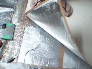
i made a "pressure sensitive" grid of digital switches, made from 2 pecies of thick aluminium foil with double sided sticky window sealing foam (see pic bottom). my problem is i am getting slow response from my "buttons". i am using a usb keyboard as logic.
the keybaord has a matrix type logic so i am running 5 rows over five columns of plastic sheets with the aluminum foil sprey gload on the inside. my frst attmpt didnt work as the conductive aluminium tape i used was too resistive, long areas and not enough current running i guess.
this prototype works mechncly but i was hopeing to get it fast enough to respond to thrown objects, like slingshot stubs. now it works only for touch. any other problems in the design?
the usb provied a current of 5v thru the usb interface.
from http://www.computer-engineering.org/ps2protocol/The Data and Clock lines are both open-collector with pullup resistors to Vcc. An "open-collector" interface has two possible state: low, or high impedance. In the "low" state, a transistor pulls the line to ground level. In the "high impedance" state, the interface acts as an open circuit and doesn't drive the line low or high. Furthermore, a "pullup" resistor is connected between the bus and Vcc so the bus is pulled high if none of the devices on the bus are actively pulling it low. The exact value of this resistor isn't too important (1~10 kOhms); larger resistances result in less power consumption and smaller resistances result in a faster rise time. A general open-collector interface is shown below:Figure 1: General open-collector interface. Data and Clock are read on the microcontroller's pins A and B, respectively. Both lines are normally held at +5V, but can be pulled to ground by asserting logic "1" on C and D. As a result, Data equals D, inverted, and Clock equals C, inverted.
Note: When looking through examples on this website, you'll notice I use a few tricks when implementing an open-collector interface with PIC microcontrollers. I use the same pin for both input and output, and I enable the PIC's internal pullup resistors rather than using external resistors. A line is pulled to ground by setting the corresponding pin to output, and writing a "zero" to that port. The line is set to the "high impedance" state by setting the pin to input. Taking into account the PIC's built-in protection diodes and sufficient current sinking, I think this is a valid configuration. Let me know if your experiences have proved otherwise.
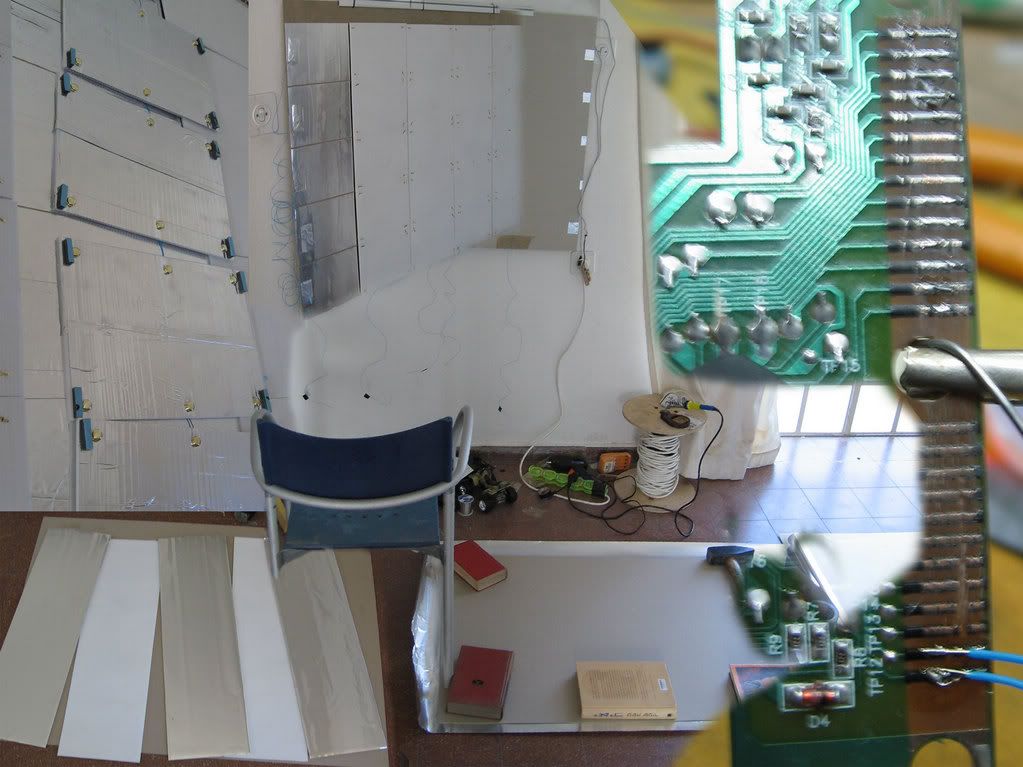
this is a montage of the work so far (500k pic)
http://img.photobucket.com/albums/v315/pixelpusher/slingshotMake.jpg
-
great work
-
looks great.
are you planing to use a custom pcb?
-
sorry.

like this one for each ressitor?
-
thanks TK

is this what you mean?
-
hi all,
i have a problem with my project.
i use the midio128 and when shorting the pins directly on the board (with a small piece of wireup)i get good results.
problem is my actual wires running to the on/off buttons are very long. some are 4-7 m long.
when i push them, i get (on some) several on/off messages. they are all traceable and reoccurring.
as i mentioned before. i use wireup cables, i need them because the buttons are very close to each other.
i had a problem managed.
these are not standard buttons but 2 pieces of aluminum with a piece of insulator between them. when applying pressure to the top foil i close the circuit.
trouble is there was a lot of on/off jitter. i fixed that by changing the debounce value in the mk_midio128_syx.
maybe i can fix these problem using a similar method?
is there something i can change that will rise the tolerance of the buttons so they want be effected by false positives?
please don't tell me to rewire :P

similar problems?
http://69.56.171.55/~midibox/forum/index.php?topic=2893.0
there's also the thread about the added capacitors. will it help stable my inputs?
-
thanks again.
i will try to help with the wiki, a lot of oldforum links there
-
revelation,
my hheart is overjoyed
i was uploading the WRONG mios128
insted of the preciuos midio128_v2_1c.zip 73k The complete PIC18F port of MIDIO128 i =, for 4 days and 4 nights was trying to upload the mk_midio128_syx.zip 11k Creates SysEx Dumps for MIDIO128: midio128.ini -> midio128.syx
it works. i whish to thank TK for you are a nice guy © and would be happy to walk your dog (if you have one).
-
TK your some kind of psychic midigod .
i wired a switch to my power supply (better then yancking it from the jampers to restart :))and i was able to get confermation to my sysbox packets sending.
to all you lost souls, confermed packets looked like this.
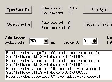
it worked for the mios1.7 upload, but for the mios128 i couldnt get it confirm, using the same method i only was able to send.
i switched to midi-ox and got this...
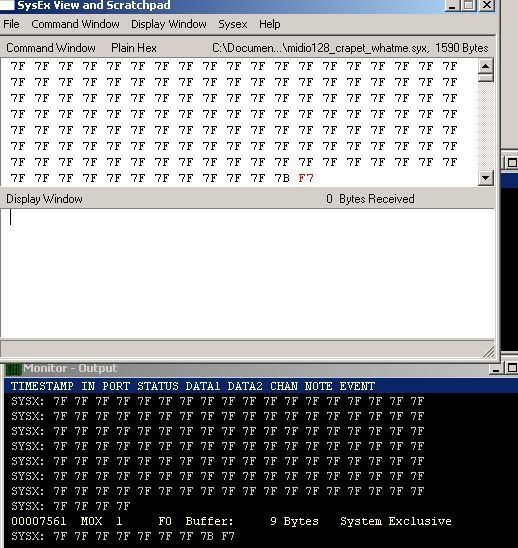
check midi-ox config, it was defulat, the guide as info on how to change it, changed...
good. but, the mios128 still wont confirm. not on any upload util.
as it stands, im preaty sure i got the mios core on the core but no application.
still trying
-
current state:
stil stuck, i get the ping when i power on the core, when in midiox.
but nothing else.
i can read and write to the pic using sysbox (only sysbox), and i get confermation on all packets.
but no midi stream
frusrating as hell, tommorw ill replace the octopelers, i already tried on several wintel systems using both soundblast thru gameport and thru yamaha usb midi adapter.
frustrating, time is ticking but my midi is not
-
UPDATE:
i got it to work by changing the device ID from 0 to 1 in SYSXBOX
i get conformation on every packet both for the mios 1.7 and the midio128 in SYSXBOX
problem now is i cant seem to find the option to change the device ID parameter in midi-ox.
those anyone have a clue? i searched the midiox forum and docs and came up with nothing.
i think i need to change that in order to view midi inputs in midi-ox for debuging before i head on to incorparate the inputs in my platform of choise, java.
-
hello everybody
i am having trouble with the uploading of the mios.
first of all i got the usual conformation "F0 00 00 7E 40 00 01 F7" every 2 seconds.
i then uploaded the mios ver 1.7 and got this errors
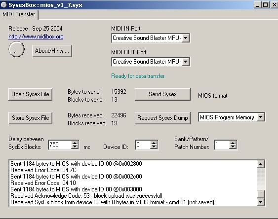
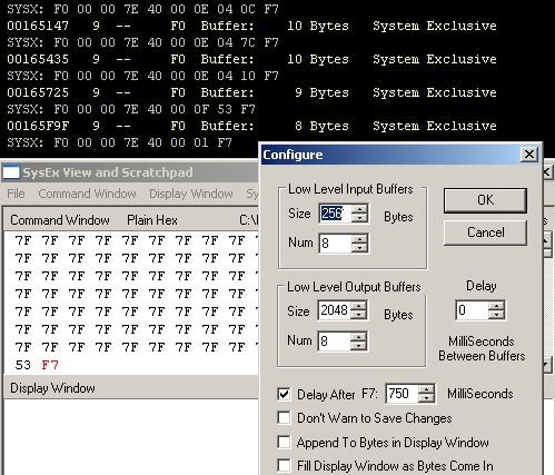
note, i get the same error in midi-ox .
i tried the midi loopback and i get the prescribed result (same same)
i built 2 cores and i tried it with both of them, same error.
i am using the soundblaster pci gameport. updated the drivers.
whats next?
i looked closely at the soldering but i cant seem to find anything wrong.
i also want to add that i get the " F0 00 00 7E 40 00 01 F7" once now, on power on.
i searched the docs and i found out the 0E04 message is related to a writing failure. is that a problem of the midi-in midi-out, the pic or something else?
-
thank you for the replay.
i thought about using that windows osscilator to test the signal.
but i cant figure it out completly.
i orignaly planed on using analog inputs for the midi and cleaning the signal after using the host program.
ill check that "schmitt trigger"
-
hi all
i am building a midi carpet based on the mios platform.
i have a peace of clothe sandwiched between to pieces of PVC. on the bottom PVC there are 90 large 20x20 cm positive charged buttons. on the other side theres a negatively charged one big piece of aluminum foil.
the carpet size is 2x3 meters.
heres a pic
the piece of cloth is a kind of resistor, only when you stand on the mat the button closes.
my problem is i only built a small scale version of this, one meter in size.
i was wondering if building it full scale will the large foil of aluminum would offer to much resistance.
i hope I'm making sense.
i guess what I'm basically asking is,
can i use the same ground source for all the buttons at the same time?
how can a measure a Resistance of a substance to know if it is too much?
i first used buttons like the ones used in ddr diy kits, basically two slabs of metal with window insulator in between which is used as a spring. its mechanical and so it simply works great, clean signal. but its to heavy and expensive at large qt. you can see on on the left of the pic.
the new system is portable and (hopefully) it will work but the signal is pretty noisy.
i think i need some kind of gate or process the signal again at the processor. (false positive and false negative are rare but they happen)
thank you for any input
yair
-
i found out more when looking for vaibration midi sensors.
look at the STRIMIDILATOR pdf on "new interfaces for musical expression" convention page.
the problem with this design is that he uses to diffrent sensors to "snese" the string values.
one is a simple linear transducer the problem with this
transducer is
Connecting the linear transducer however influences thebehavior of the string. Initially the linear transducers also
contained a spring inside, which caused the transducer to
pull at the string. As this was an undesired effect, I removed
this spring from the transducer. Even with the spring removed,
the transducer still influences the string in such a
way that the string can no longer vibrate freely.
this si unacceptable for the harp losses its acoustic abilities.
as for the vibration sensor this design used
For detecting the vibration of the string, another solution
had to be found. I chose for a conventional way of translating
vibrations into an electronic signal: a coil that one can find
on any electric guitar.
http://www.music.mcgill.ca/musictech/nime/onlineproceedings/TOC.html -the convention
http://www.music.mcgill.ca/musictech/nime/onlineproceedings/Papers/NIME03_Baalman.pdf -direct link to the pdf
http://www.nescivi.de/research/nmi.html -research page (other intresting stuff)
-
hi all, new guy
i got a friends idea i want to implement, he plays a 32 string harp and would like to turn it into a midi harp.
i saw a couple of examples googling for the term, one guy (with a solid design) wants 5000$ for a costum made one.
my question is what kind of sensors can be used for such a task? i originaly thought of midi guitar pickups, as in magnitic resonnace.
is that the way, i dont know.
http://www.kortier.com/midi32.htm
hope to hear from sombody,
peace
yair
resistance problem?
in Testing/Troubleshooting
Posted
TK, i couldnt find a referance to a sm_example2 anywhere in here or ucapps.
i will try to connect a midibox interface i have and check i want it super low cost for handing out to kids that cant efford smashtv prices ;).
i still hope i can implement stryd idea. ill look into it.
http://www.soundonsound.com/sos/mar04/articles/synthsecrets.htm
to show my love for the forum, here is a mini controller i made from a cigar box (very good material to work with)
couldnt find a better place to post this(?)