

moxi
-
Posts
993 -
Joined
-
Last visited
Content Type
Profiles
Forums
Blogs
Gallery
Posts posted by moxi
-
-
Hi,
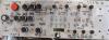
I'm selling this little beast :
I let you debate about price...
Also, I will join another sid module (with SID chip) with the machine, in case some genius can find some more room inside the box ;-)
All my best!
-
salut,
pour les connecteurs, celui de ton lien n'a que deux ĉontacts (faut pas se fier à la photo), et les terminaisons métalliques sont vendues séparément. 5 contacts c'est mieux.
pour le bouton ça a l'air bon.
a+
-
salut,
essaie de régler les potars contraste et intensité sur le module core, c'est peu être juste ça..
-
...moueh...ça remplaceras pas le plaisir de faire un truc intelligent de ses dix doigts ! ;-)...
-
fait juste attention chez farnell, les prix sont "hors-taxes" et les taxes sont rajoutées au dernier moment quand tu valides la commande...à moins que ça ait changé depuis...
-
Hi,
I've done a lot of job starting from analog toolbox application : inter-modulations between EGs and LFO's, LFO's by LFO's, MIDI note synced EG, bpm LFOs and much more..all this "digital" routing and modulations have been tested and verified with a scope, with standard Aout CV module. probably there is some detail issue due to my crappy way of programming, but that should do the job..you won't burn your analog gear using it ;-) ...
take a look at :
the app archive is at the bottom of last post, take a look in main.c where butons fonction are quickly explained.
Best regards.
-
Salut,
dans tous les cas, il te faudra souder les composants sur les circuits.
1 PIC18F452 9.95$( la ou il y a marquer : PIC ID Calculator ,PIC ID header(s): je peux laisser : 0000 0000 0000 0000 ? )ouep.
Pour l'alim, le plus simple c'est de prendre un transfo universel (ou tu selectionneras 9V) , 500mA voire 800mA si ton/tes LCDs consomment beaucoup (check sur le net la différence entre les volts (tension) et les ampères (courant), ça te servira longtemps!!
pour les pads, lumineux : sparkfun en fait, c'est juste diablement chéro..puis c'est juste des boutons, pas vraiment des pads, même si du code sur Ucapps te permet d'émuler une réponse type vélocité (algo basé sur le temps de pression, pas sur la force de pression à proprement parler)..
-
salut, et bienvenue..
pas besoin de module AIN, tu peux utiliser le port J5 du module core pour connecter jusqu'Ã 8 pots/faders. Le module LTC aussi n'est pas utile, si t'as besoin ni d'un second port MIDI Out, ni d'un port MIDI Trough.
Pour l'UC16, essaie plutot de la vendre telle quelle pour avoir de quoi commander des pièces neuves à ta convenance, C'est toujours un peu bête d'abattre une chèvre pour avoir une vache ;-) ...
Pour les encoders, VOTI.nl ou smashTV...entre autres..
hipHoôo!
Moxi (not Fukushima related).
-
-
Necro bump.
humm.. Nils...It's maybe a too early for my necro..maybe it's just right about the Moxi-interface...;-)
But it's now too late to change my name here, heheh! :ninja:
much Love!
-
re,
pitit conseil si c'est ton projet electronique:
divise la tâche en petit "stade", example, commence par le core et le LCD, charge une appli au hazard, ça marche : branche un module de plus (un din, sans boutons ni encoders, ça marche: branches tes encoders/buton...ainsi de suite...le pire et souvent le plus difficile, c'est le débugage.
Prend un pic 4580, ou 4620, tu pourras tester les applis plus récentes et plus lourdes aussi, c'est plus prudent aussi en cas de mise à jour..
bon ok, j'arrive un peu aprés la bataille..mais comme on dit mieux vaut bon vomi par terre que jamais ;-) ...
-
petit rectificatif pour les potentiometres
en fait les valeurs de 1k a 250k fonctionnent
seule la consommation finale change
salut..
la résolution de la conversion aussi, car les adc's du pic si je me souvient bien se basent le courant (amperage) et non la resistance.
-
hello,
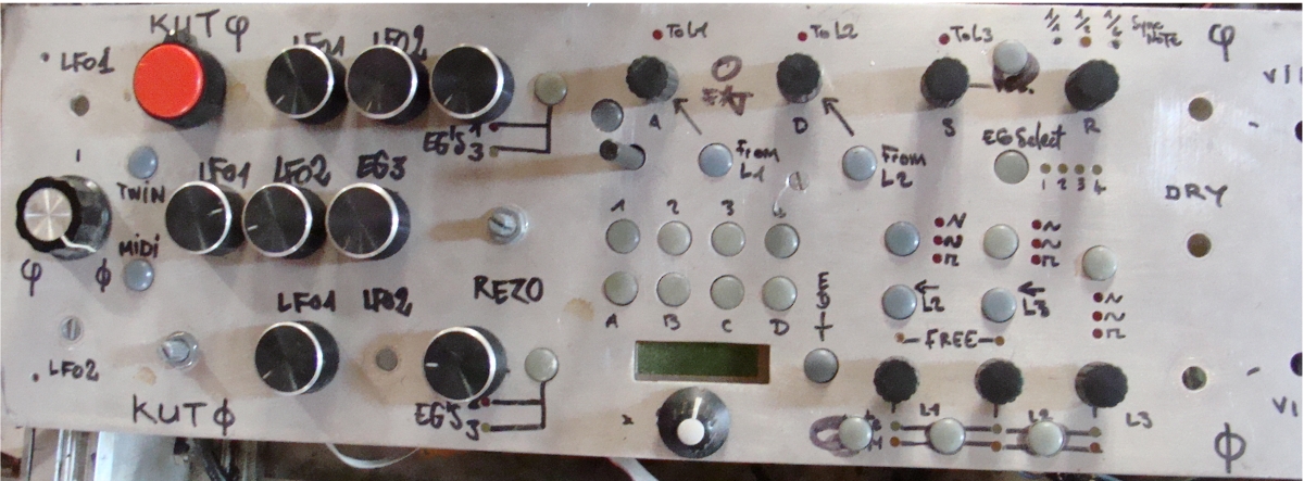
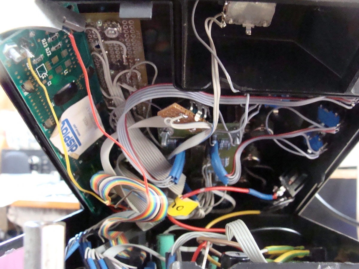
I update this thread, cause some works have been done since, I've finished the whole CS, and the resp. programming. It have been tested and all seems to work fine on the logic side. So I think it's good to share it.
I won't go on this gear before some months cause I have a lot of things to do, and it will need all of my attention and concentration, what it's not possible now. but rather than keep it under dust...
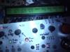
I attach the app and two little pics, as I've ripped some part for other project and be not able to light it up now, I put a little pic I've take last year with some leds lighting and the LCD...
Lot of inter-modulation have been added, cv and audio mixers have been build , but not tested. Just some tests to directly modulate the cem3378 and to check modulation digital mixing have been done..far to be finished!!!
I've added and do the testing with 2x40 LCD, more comfortable, but get no room on the painfully DIYed control surface, I keep this difficult choice for later, when maybe I will get enough dollarz to make a full new CS...
A bankstick and a preset handling is now present, by some way I'm proud of it : you get access with only one buton act to 4 preset, one time you're in a bank, or with two pressing if you have to select another bank, saving it's quick and easy too (just acts on digital mods, of course, analog pots of cv-mixers and audio won't be saved, maybe the new stm32 core that can support more cv's module will be the trick to solve that..but a lot of rework should be necessary).
The MIDI implementation is not finished, an internal bpm sync is present too, but no way to remember if I have tested it..
You will learn more reading the code, I'm open to possible optimisation, I know I tweak the codes always in a rough way, it's cause mathematic and me are two different thingz..
Another thing : the MBsid already can do all of this, so maybe this crappy app is useless... :frantics:
All my best.
Moxi.
-
Hello,
I'm back (from where? )..
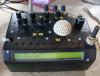
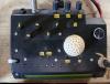
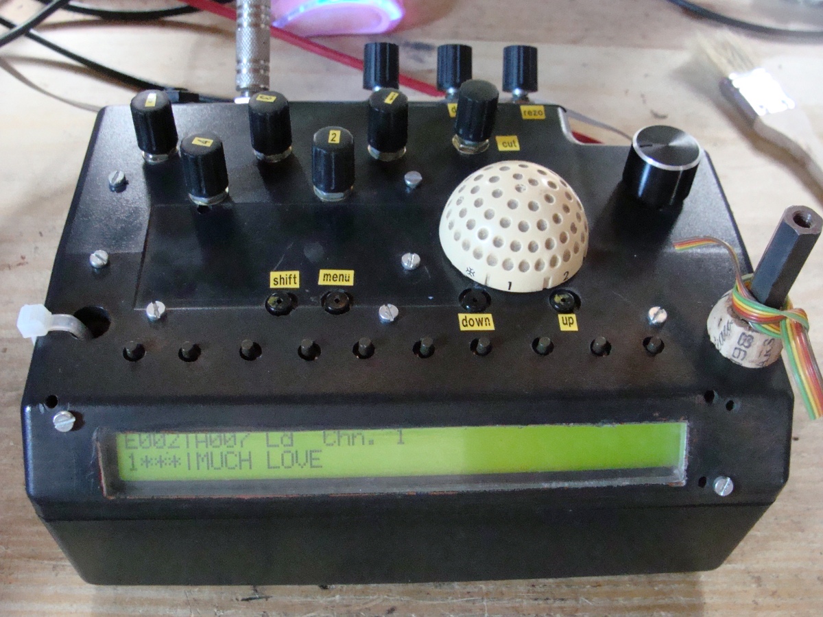
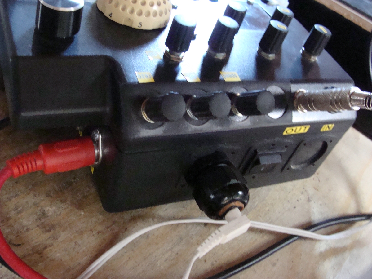
I present you my first SID,
It was supposed to be a gift to the "Glistorp" man (http://fr.myspace.com/#!/glistorp), that learn me some great things, unfortunatly, I never see him again, maybe one of this dayz...
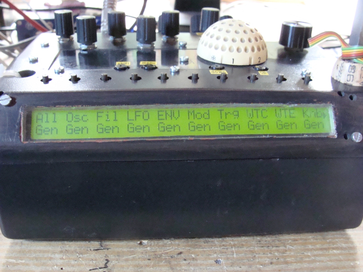
So I've buil it robust, and organized for glitch and random sounding. The nice "gen" page, with this big LCD and the resp. selection butons allow direct access to random of each section, that's really fun to use, especially in drum mode, where you can keep the rythm and change the glide, or notes, osc's...or want you want (and so what want the SID)
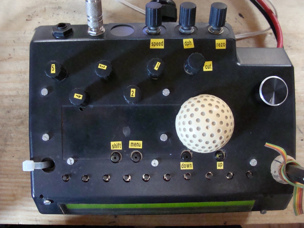
There is 5 analog pots (marked 1 to 5) that you can randomly assign too, so, one time you press the resp. sel buton, you won't know what you are goin to tweek, and sometime some strange behaviour appears as soon as you have pressed the knob "gen" buton (side effect? maybe an option to freeze pot reading during the change of assignation could be a good thing? but I'm not sure, does "clean" chaos is still chaos??...
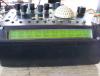
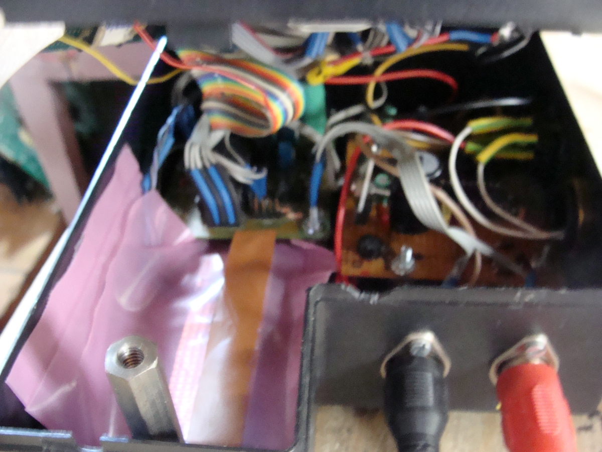
filter and LFO 1 get their dedicated buton, but it's boring that the 6581 get a so crappy filter, hopefully, I still get room to add an analog one later, but about filters, I have already more ambitious projects on the go, so...
The big white "golf" half-ball come from an old home heater and this purpose is to play/stop sound or sequence. It's Glistorp who found it in a trashbin of the big town..Let say this big buton get something magic, but I can't explain that more precisly, only the rare person who push it can understand what I mean..
One more Time, thanks TK, SmashTV and all other great peoples here.
Moxi.

-
hi,
my first experiments with this one:
http://www.soundandbreakfast.org/diy/n1487816091_30084961_2100876.jpg
:
http://www.myspace.com/solaireparallel
:-)
-
yes, it's relative event, try with the other example..
-
hi,
take a look into the main.c file :
/////////////////////////////////////////////////////////////////////////////
// This function is called by MIOS when an encoder has been moved
// incrementer is positive when encoder has been turned clockwise, else
// it is negative
/////////////////////////////////////////////////////////////////////////////
void ENC_NotifyChange(unsigned char encoder, char incrementer) __wparam
{
}
as you can see, in this app, there is nothing programmed to do something when an encoder is moved..so you have to add some code yourself:
examples:
-
salut,
tu as des switchs TTL (0-5v) pour l'audio (ssm2404: http://www.analog.com/static/imported-files/data_sheets/ssm2404.pdf) j'ai testé ceux-là en les pilotant simplement avec un module DOUT.. ils sont "clickless" en plus...
-
salut,
le module cv te permet de récupérer les lfo's et eg's du mbfm en analogique, tu n'as pas de pots ou d'encodeurs à ajouter...
La page AOUT permet d'assigner les sources de modulation d'instrument à un canal AOUT. Notez que les sorties analogiques (CV) sont une option qui nécessite l'installation d'un module MBHP_AOUT .
* AOUT: sélection du canal AOUT que vous souhaitez configurer (1-8)
* Inst: assigne un instrument (1-4) au canal AOUT
* Assg: assigne une ou plusieurs sources de modulation à ce canal AOUT (L: premier LFO, L: second LFO, E: Envellopes EG5) -- le taux de modulation doit être ajusté dans les menus LFO/EG5 , ce dernier paramètre est sauvé avec le Patch Instrument
* Offs: ajout d'un offset aux sources de modulation (-64..63)
Autre question: sur les pcb des filtres, il y a 2 audio in et 2 audio out, donc, je suppose que je vais brancher les 4 sorties audio du module FM sur les 4 entrées des 2 dual filtre.Et les sorties des filtres sur les jacks out. c' est juste?oui, et tu peux coupler les sorties par deux (stereo) si tu veux en réalisant les mêmes assignations pour plusieurs sorties cv
-
a priori, si t'as pu souder les socket de l'un sur l'autre, c'est qu'il y a le même nombre de pattes, non?
...enfin bon...on est tous un peu con, mais ceux qui le savent finalement le sont un peu moins!! ::)
-
Tu utilise quoi pour souder tes potars au module AIN ? Parce que j'avais lu qu'il fallait directement les souder sur le pcb sans utiliser de cavalier mais c'est vraiment trop casse c**** !
je pense que tu fait une confusion avec le fait que certains recommandent (notament pour l'audio) de ne pas utiliser de socket pour les AOPs et autre ICs, je vois pas trop la difference entre utiliser un SIL et souder directement le cable au PCB (sinon la prise de choux, comme tu dis..)
Mais là c'est plus grave en fait....Mes soudures n'arrêtent pas de se barrer !
soigne ça d'abord! cherche sur le net, y'a des tutoriels pour bien souder et savoir distinguer une soudure foireuse d'une réussie...
Ah et oui autre question : c'est quoi la meilleure méthode pour connecter l'alimentation aux potars?
Parce que moi, j'ai connecté le vd et le vs de chaque registre sur un des huit potars, et aprés j'ai fait des sortes de ponts entre les 7 potars qui restent. (oui c'est pas trés clair)
http://www.ucapps.de/mbhp/mbhp_ainx4_64pots.pdf
ta méthode semble correcte..
en tournant un potar ça transmet plusieurs cc différentsdes court-circuits, surement coté PCB, là ou tu as soudé tes cables directement sur le circuit..
et don't worry, ça finit tjrs par fonctionner, une MIDIbox!
-
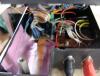
no name, the psu was inside the keyboard.
it's a standard design based on voltage reg ("78mr05r" and "78/79m12ml" ), and there is one flat cable per voltage (each with a ground line), there is a ceramic blue line-filter capacitor just after the 240v input.
i use AOUT_LC.hum...I was using Aout_LC module when doing my first test where the filters generated sound themselves, I can test if the same thing still happen now with the normal Aout module, but not before a pair of week, I still have to finish the prog and rewire all the knobs/button..
quote from Ucapps Aout_LC page:
Another typical problem of cheap DACs (not only of this circuit, but also for cheap integrated DACs) is, that there is some "zipper noise" each time a new voltage is selected. The intensity of this noise depends on the bits which are toggled when a new voltage is selected - the leftmost bits (most signifigant bits) will produce the highest zipper noise. Even I can see this noise on my scope, I haven't noticed an audible effect with a discrete Moog- and CEM3378 filter, yet.
that could explain the noise..
-
If i press my fingers on the chip...this sweeping noise will be more or less boosted.
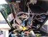
maybe for that you can try to improve your ground circuit, make larger traces and design your circuit in "star", with all ground line reaching each other the nearest of the start point at the PSU. I cannot help you here cause I use a nice PSU ripped from a roland keyboard.
The second noise is a repeating sound in background, like a train drives on the rails.sound like what I get too, but only when cv's set at full...what the frequency of this sound on the scope? if 50hz (or 60hz if your are in USA), we can suspect some side amplification of the 240v buzz? else, maybe the DACs generate transient noise, the max 525 datasheet say that:
Digital or AC transient signals between AGND and
DGND can create noise at the analog outputs. Tie
AGND and DGND together at the DAC, then tie this
point to the highest-quality ground available.
Good printed circuit board ground layout minimizes
crosstalk between DAC outputs, reference inputs, and
digital inputs. Reduce crosstalk by keeping analog
lines away from digital lines. Wire-wrapped boards are
not recommended.
..but the original Aout pcb seems to be already well designed in this way... maybe you use a diy "Wire-wrapped" board ?
-
Malgré ça, quand je tourne certains potars je reçois des infos sur plusieurs canaux...
c'est à dire? le même CC avec la même valeur sur different canaux midi, ou bien en tournant un potar ça transmet plusieurs cc differents?
as-tu bien mis sur "1" le flag "#define DEFAULT_ENABLE_AIN_MUX" dont on parlait il y a quelques jours?
si oui , es-tu sûr que la compilation c'est bien déroulée aprés les modifs de tes fichiers? (fait un "make clean" d'abord, puis un "make"..

MIDIBOX of the Last Week: One Mono SID
in MIDIbox of the Week
Posted
Hi,
I send you a PM..