

ziGi_cro
-
Posts
5 -
Joined
-
Last visited
Never
Content Type
Profiles
Forums
Blogs
Gallery
Posts posted by ziGi_cro
-
-
Good thing you left that big blank space on both sides of your panel then :D
Its too obvious, ill have to fill up that space.... but i dunno where to find big round spin caps..
And i wasted so much time on that plate, its brushed aluminum 6 mm thick and now i want to change layout (too late).. and the worst part is that its giving me hard time implementing the buttons... i have 40 9x9 mm click buttons and I dont know ow to put them... Tryed glueing with epoxy but they refuse to hold after few clicks.. :(
-
I havent been aroun for long time here... And at the time I tought I am the only guy making midibox for traktor... But when I returned first thing I saw is your thingy in the gallery, and I have to admit, I was full with envy :-[
Great stuff man, nice realization, and am not even mentioning functionality , because your project is 1 to follow... Respect
MINE

YOURS
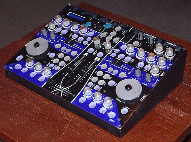
Ill have to redesign mine :'(
btw I didnt know for shure that encoders could be implemented for use in TRAKTOR for fast forwarding and reversing....
-
This is my story....
When I first connected the JDM and did the measuring procedure i had realy strange readings. I red every post with JDM troubleshooting and loading up a bootloader. I tried everything that was posted here, tried 8 computers, external power and so on . I didnt giv up, in 100 combinations of settings and io drivers only one worked.
This are my readings from pc at home (settings mentioned in ucapps page/JDM MODULE)
PIN 1 (MCLR#) - PIN 12/31 VSS = 12.9V
DURING READING = 1.5V
Other reading where probbably fine (MOST TROUBLE I HAD, I HAD WITH MCLR AND - PIN 1)
PROGRAMING ERROR
NEXT TIME A STARTED IC PROG
PIN 1 (MCLR#) - PIN 12/31 VSS = 0.5 V !!!!
PC WITH WIN 98
PIN 1 (MCLR#) - PIN 12/31 VSS = 0.5 V !!!! Same thing!!!
ANOTHER XP PC
PIN 1 (MCLR#) - PIN 12/31 VSS = 0.5 V !!!! Same thing!!!
So I accidently, while I was measuring, MCLR voltage I started with moving the cable and i dicovered voltage rising up to 14-15V and back again!!!!
The cable was new and I was fine, conector too, and everything else.
So I knew there is some how a way to get 14-15V on MCLR ( with no external power), and during the reading too.
After that it hit me, I dont know where from: I`ll try IO delay mode : 4 !!!!!!! (THAT IS THE ONLY DELAY VALUE THAT WORKED!!!)
THESE ARE CONFIGs (XP WIN)
IO DELAY mode : 4
TALIO SYS driver (http://www.talkingelectronics.com/FreeProjects/MultiChipPgmr/MultiChipPgmr-P3.html) - instructions on the site
WINDOWS API
Enabled MCLR as VCC (I2C menu)
Enabled Vcc control for JDM
THIS IS HOW I GOT MY JDM WORKING AND PROGRAMING the PIC !!!!
Best regards thorsten, I hope this will hel others because we all now how can JDM be frustrating. The JDM is a final stage in any MIDI box project, and when u get everything done, all you have left is PROGRAMING the pic so you get crazy when it doesnt work. (I did!)
ziGI_cro
-
Hi there...
first, sorry for my english.
it is 2 am and am crazy.
I have a same problem, but i don use a COM/usb converter.
Using no external power (because ther is no diference)
XP user, also tried with WIN 98, tried with TALIO.sys and USERPORT.sys drivers
The voltage`s are:
VSS - MCLR# - Once I had 12.5V when i used TALIO.sys drivers but after READING a pic everything came back to voltage : 0.5V
VSS-MCLR# (during reading - 3.5V (but when, am guessing,Talio didnt work, i had same 0.5V )
so anyway tried to program it but it didnt work
other voltages are in normal range
MIDIbox of the Week (MB64E based Traktor Controller made by PayC)
in MIDIbox of the Week
Posted
u all seem to have lil factories at home... heavy duty equipment... ;D