

gavgomad
-
Posts
49 -
Joined
-
Last visited
Content Type
Profiles
Forums
Blogs
Gallery
Posts posted by gavgomad
-
-
Nice to know I wasn't too far off! ;-)
Well, it seems to me that logically we should follow the datasheet and go with 33k/20k solution also used on the 3378/3379. At least that way we know that the filter should be responding appropriately to a 0-5v control signal. ;-)
Maybe, as you say, there is a different CV scale going on inside the Xpander.... All the more reason to go with the datasheet given that we're coming straight out of the DACs and can set our own upper and lower limits and scaling both with the hardware trimmers on the DAC board, and in the software.
As an update, I have been working in my spare time on a dual 3372 board (still plugging in the schematic into Eagle - itself a slow go!). As per a recommendation from one of the good lads on the SDIY list, I'm using a single DG403 and DG407 to handle the switching on both filters, with 3x TL-074 and a TL-072. It's gonna be a nightmare to layout, but I'll take my time and see what I can do! ;-P
I have all of the switching circuit plugged in as a schem, and one of the 3372 filters (went with the datasheet!) - one more to go! Will post the plugged in schem when I'm done so my work can be checked and parts decisions made before we move on to layout.
As for the Obie caps, I'll give the 3389 sheet a look.... The caps selected appear to be the same as the 3372 datasheet, but for the switched in 100pF in place of one of the .033uF in half of the modes.
-
Thanks guys! Now, to plug in the numbers and figure what it means....
Firstly, the variation for the input voltage seems to be in the first part of the equation (first brackets - 0-v) correct? Accordingly switching between 0 and 5 here should give us the respective output at 0 and 5v respectively.
My math sucks, and I too am not an EE, so bear with me.... My results might look a little funny....
For the 20k/33k as in the datasheet, if I set the output to "0V" as in your equation, I get v=-.14025 (close to the -150 you were referring to?). With "5V" at the output, I get v=.0911641, which is a little more distant from the upper figure of 110....
Now, for the OB (38.3k/196k/), I get v=-.0247381 at 0v, and v=.101859 at 5v.... Seems that they have "biased" the filter a little more open, or are my maths completely rotten? OBs have always been capable of some pretty bright buzzy sounds, as well as dark deep sounds....
Does this sound right? Which is preferable to others?
Sorry for my thickness.... I'll get there in the end! ;-)
Gav
-
Hey Olga42! Sorry for the tardy response to your helpful post! ;-)
I hope I'm not late to the party spoiling something.
Never! We need all the help we can get! ;-)
I just finished a filter using a stereo pair of CEM3379s and couldn't help but noticing the similarities in biasing. The VCF CV is a small signal input so all that is done using the resistor network is some biasing. For instance on the 3379/3389 the VCF input needs to stay in between -155 to +110 mV for a CV input of 0 to 5V before the resistor divider (if we go by the data sheet looking for a control range of 14 octaves). The CEM3372 has exactly the same recommended signal range and its' data sheet shows exactly the same resistor divider of 20K with 33K to Vee and 1K to GND.
So theoretically, then, and in light of what others seem to be doing with the 3378s and 3379s, maybe the most sensible solution is follow the datasheet in this regard? Use the recommended rails and biasing from the datasheet, and just incorporate the switching and buffering circuits further down the line....
I don't have my lab notes in front of me so please bear with my lack of maths at this time; but circuit analysis of this type of divider can be done using the fact that the sum of all current at any point in the circuit is zero - current into the point equals current out from the point. This means that current in to the VCF CV pin on the chip will give a voltage of around -150mV when the CV signal before the 20K resistor is 0V. Solving this for a +5V CV we get close to +110mV. This is the old manufacturer's data sheets so far. What has been done by Oberheim and others is probably just a re-biasing to fit their chosen CV range.
My theory is horrid.... But a query - what would the real difference be between the OB biasing and the one on the datasheet? Is the OB circuit pumping out something more than 0-5v? It seems that careful setting of the maximums on an AOUT_NG board prior to connection ought to make more sense than scrambling around with resistor values for rebiasing purposes....
Hit me back with questions if this makes no sense so that I can retrieve my lab notes where the formulas exist.Is there any way you can show the formulas? I'd like to plug in those values from the OB and see what the difference is.... I wonder whether or not their DAC is 0-10v or something, and accordingly they need a steeper divider....
How about the -5V needed? Couldn't there be a local regulator on your board to generate this?I think this is the way I'm going to go now, and hang it off the -12v rail, which probably isn't under heavy strain anyway. ;-)
I was just looking at Rio's 3379 schem and board.... Maybe I'm making this too hard.... Follow the datasheet
until we get to the switches and buffers, and rely on the AOUT_NG trimmers and the AOUT setup routines in the software to set the right CV levels.... ;-)
Been bogged down at work again, but as I've had a bit more success with the ol' Eagle program, I think I may try again at this on the weekend.... Starting to find the PCB work kind of fun! ;-P
Thanks again olga42! Will try and make my next post in this thread a little sooner than my last.... Hopefully I'll have an ugly design for the pundits to comment on! ;-P
Gav.
-
Hey all,
As I'm finally getting my 6582 built (ie. need supply to start testing!), and as I need to include a -5V rail for the "to-be-incorporated" 3372 Xpander filters (x8!), I was wondering how difficult it would be to simply add a 7905 -5V regulator on to the circuit?
My thought was to simply add a similar circuit to that used to for the +5v and +9v circuits, but I doubt we'd need to add a heat dissipation resistor, as I don't believe that even 8x 3372's would draw that much current.... Anyone see any probs with this idea? Are we going to destabilize the whole PSU by adding another rail? I think that with a little stretching of the board, the new rail could be grafted in below the power diodes....
Gav.
-
I've got to let this sink in, but got no time tonight.
But I do know that the 3372 is also used in the prophet 600 and the rhodes chroma polaris. I attached the filter schematics.
Thanks much!
After reviewing a few different applications of the 3372, and the datasheet, I think that there is just no way around having a -5V supply for this filter. I still need to compile my thoughts on my own PSU for my 6582, but maybe modifying the design from northernlightx to add a 7905 as well....
In reviewing the minimum requirements for the positive supply, it has to be +9.5 or more. That rules out a -12 to +9v supply, and I think -12 to +12 is just a little too close to the 25v rail to rail incineration point of the 3372. Accordingly, must supply a -5V rail to the board.
This will eliminate some other problems though with value subs. ;)
Now, I just need some practice with Eagle.... ;)
Gav.
-
Glad to see this is still happening. I wish I could offer some knowledge here, but this is pretty much outta my league, so I hope to learn a lot.
Hi Luke.... Slowly but surely! It's actually out of MY league, but I'm willing to press on and see how far we can get before we are stumped! :D
Gav.
-
I'd be using mine as part of a filterbank and not restricted to the SID, so I like the separate boards thing.
Well, maybe some form factor discussion is in order. This will be a long one, but hopefully will spark some discussion on where we want to go....
I am definitely a fan of doing a two-board system. Board A = Dual 3372 VCF/VCA; Board B = Dual Multimode Switch Board. I think I may opt to put the cell buffers for the Xpander mode on the 3372 board, to be jumpered in and out, that way we have a buffered signal before it travels along any wires to the switch board.
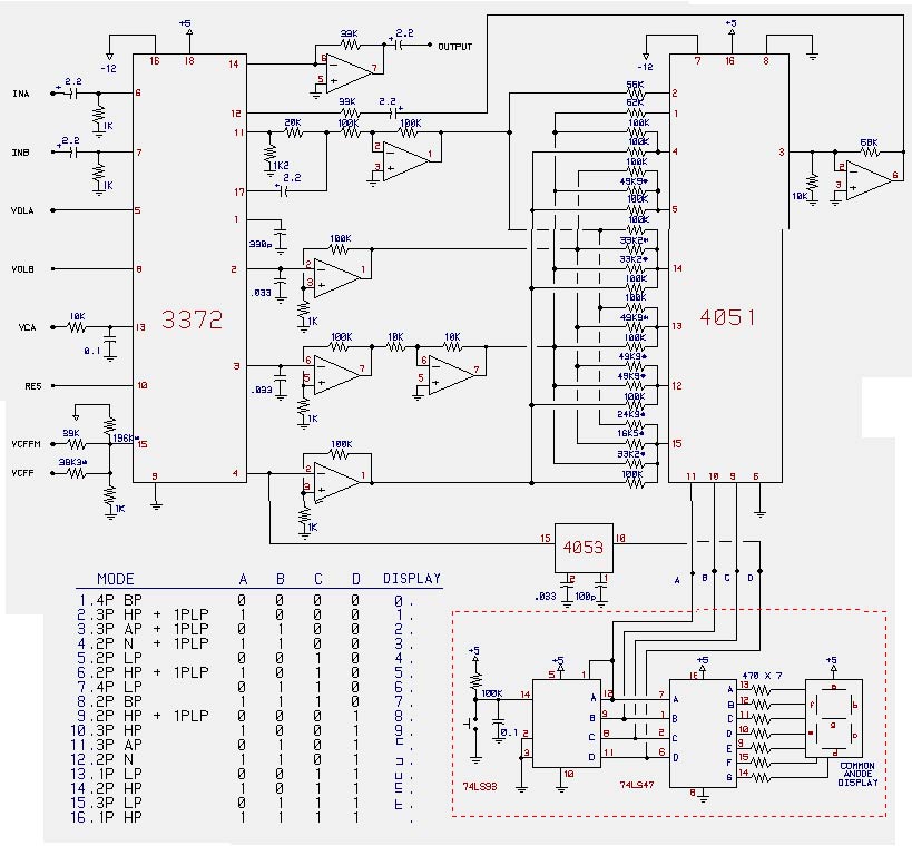
Let's discuss Board A first (I think Board B will come naturally, as really its a direct copy of the 4051/4053 circuit from the Xpander service manual).
The 3372 is equipped with the following:
- 2 Separate Pre-VCF Audio Inputs w. CV Control of Input Volume
- VCF w. VC Resonance (Resonance is not exponential, so no linearization required!)
- Final VCA w. CV Level Control
For switching the audio routing (ie. SID thru vs. 3372), a similar relay circuit to that seppoman used on the 2044 board would suffice.
I also think that it would be beneficial (and easier on the design side!) to, as seppo did with the 2044 board, make use of the scaling options on the AOUT NG, which this will probably link up to, for fine tuning and offset adjustments. This will avoid the necessity of trimmers for each of the CV functions on board the 3372 PCB.
MIXER INPUTS
Even though I don't have any particular intention of using more than one input or the volume control, it makes sense that we provide facility to use the other input and volume controls. For the audio inputs, perhaps a jumper to ground where you're not going to use the input. For the CV Mixer controls, perhaps a jumper which can be installed either to ground (to silence the input), or to app. 4.88v to use full volume (makes sense if you're strapping on to the SID for example), and if the jumper is not installed, the middle pin is your connection point for a variable CV?
Standard setup for the SID setup would be, for example, SID output (via switch or relay) to Input A. Input B jumpered to ground. Mix CV A jumpered to 4.88v (essentially full-on), Mix CV B jumpered to ground.
VCF
I have already discussed the bizarre "biasing" thing going on with the CV input. If anyone sees anything wrong with the following let me know.
It appears that all that is happening at the front of the Xpander circuit is a slight biasing of the input voltage by -.0253807.... volts by way of a resistive divider (196k and 1k for -5V). To keep this same figure with a -12V feed, we'd need to up the 196k to a 475k (if my maths are correct?) to give us something close (exact value is 471.8k).
Other than this, there is a simple divider on the front end (38.3k, 1%), using the same 1k resistor to ground. This maxes a +5V input out at 4.872V. We can keep the same value, on the presumption that the Xpander feeds a 0-5V control signal, and that this is what we will be adjusting our AOUTs to.
Resonance seems to be a standard 0-5V input, and seems wired direct to the DAC on the Xpander.
VCA
Although the VCA is independently accessible (it's own I/O), I don't see much point to adding a separate relay for accessing the VCA alone.... Personally, I don't see that it's worth the effort.
In any event, there will need to be (as with the cells - jumper = connection to the on-board filter caps, no jumper = pin to the requisite buffer and on to the switch board) a jumper here to either route the VCF in, or the Switch Matrix output....
There is a little bypass network on the Xpander circuit for the VCA level CV, so for continuity I say we follow that.
Did I miss anything??? ;)
Gav.
- 2 Separate Pre-VCF Audio Inputs w. CV Control of Input Volume
-
Hey all!
I actually HAVE been pondering this some more in my absence from the boards.... REALLY! ;D
Frankly, I appreciate the bump though.... Unless its for the day job, I can REALLY procrastinate! ::)
I'd been thinking about this too, but I quit it because I had no idea how to switch the filters with the midibox software. Would be cool though.
As stryd_one indicated, the switching in the software isn't too bad.... 4 bits needed, so 4 external switches ought to do (nicely provided for in the SID patch architecture).... For my purposes, I'm more than happy to switch in pairs, so that only 4 of the 8 external switches are used per SID engine, leaving 4 per engine for other things (gates, output or effects switching, etc.). TK already offered the sweet idea of creating a wavetable to "count the bits" so that you can arrange the modes in any order you want and, if desired, modulate through the sweep (recalling that you are still going to be hard switching between modes - no interpolation here!).
It would be nice to have a dedicated parameter in the i/o to give visual feedback of filter mode though (save a LOT on getting individual 7-seg displays and counters to let you know what's going on in there....)
As for the filter, I think I really need to experiment a bit with the filter sans the switching circuitry first. I was actually re-considering whether or not to do this in two parts - one PCB with a basic buffered 3372 4-Pole Lowpass/VCA, but use SIL headers with jumpers to configure it so that removing the jumpers opens the circuit, and with a few connections, hook up to a dual switching daughterboard with the CMOS switches, extra stage buffers and resistor networks. It seems that this should be doable in light of the daughterboard used for the MOTM 440 filter....
I first thought that it would be better all on one board, but as I need to "suss-out" the 3372 a bit without that circuitry anyway, and there may be some folk simply looking for yer basic SSM2044 style circuit (potentially more compact board as no linearization is needed!), this approach might be best. Also, you can simply upgrade things at a later date by adding the switch board! I'm open for comments and cautions here.... ;)
Certainly haven't decided one way or other on this one yet!
My first concern on the filter is the supply and biasing (the 3372 circuit seems to want to see some -V at the Cutoff Freq CV In).... The Xpander filter (and the datasheet example) uses -5V/+12V. It would be MUCH easier to run this on -12V/+5v, but I don't know how safe this is, and it WILL change the CV input scheme (unlike the EFM Xpander example - I think -12V, even through the 196k etc., is still not good anywhere near an input which is looking for 0V to +5V....)
That being said, I don't know I'd want that +5V rail near the 3372s, as there is bound to be a LOT of potential for digital hash on that line? The 3372 apparently can take 25V total supply swing. Maybe -12V and +9V? Keeps us in a more "safe" zone, and on a less noisy rail (I hope? How much hash is there in the SID supply lines?)
Anyway, I'm off to dig up some other 3372 designs to see how they were done.... Maybe some other designs will give me a bit more insight.... Will report back soon! ;)
Gav
-
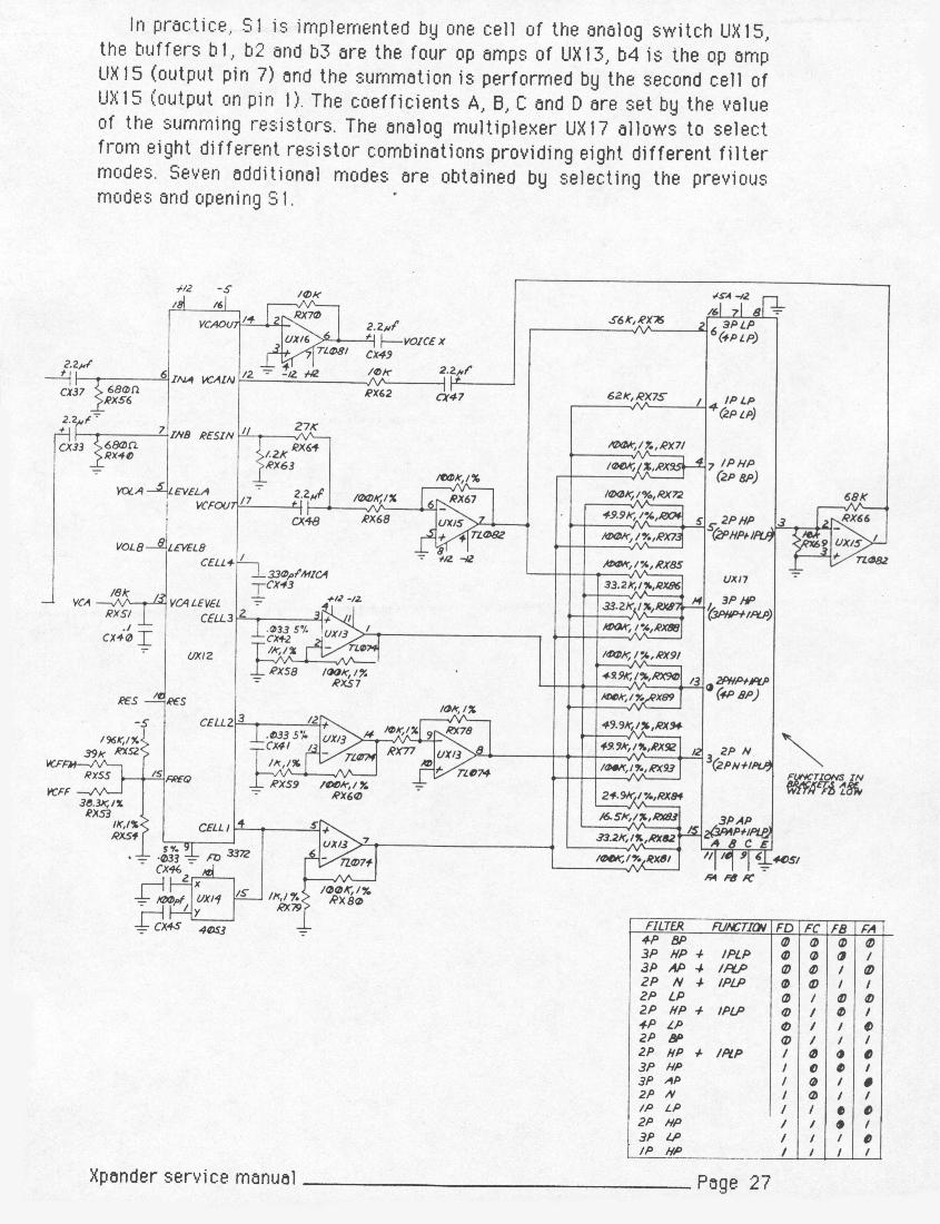
OK, so here is my previously posted (in electro-music forums) surface comparison of the original Xpander circuit, and the "EFM-ized" version. If all goes well, the page from the Xpander Service Manual, and a "cut-and-paste" version of the EFM version should be attached at the end (they're not too large - my first attachments here, so hope I'm within the rules!).
Here are the differences I noted, and what (in all my naive glory!) I think it means - EE folks, please stand up and help me out here! ;) :
Audio Inputs
EFM inputs have 1k resistor pulling to ground after the 2.2uF electro, whereas the Xpander only has 680 ohms to ground. Not sure how critical this would be, and may be a "convenience" choice by TomG, as I'm sure he had far more 1k's around....
VCA CV Input
EFM has 10k resistor on the input pin and 0.1uF cap to ground. Xpander has an 18k resistor instead, with same 0.1 uF cap to ground. Presumably all this would do is alter the sensitivity of the input, no? The EFM would be a tad more sensitive?
VCF FM CV Input
BOTH have FM CV going through 39k resistor, and Cutoff CV through 38.3k to input pin. EFM also feeds the input with apparently -12v through a 196k resistor to input, with 1k resistor to ground. Xpander does the same, but with -5v.
This is a big one for me.... Why the difference in voltage, or is this an error in the EFM schem? Frankly, -12V will sit better with my supply design in this instance (as my supply is based on the NorthernLightX design). It seems like this network is some sort of biasing of the CV inputs....
Also, a general Q - if only 1 input is needed from DAC, what should the CV input config look like like? I assume the -5V/196k and 1k to ground network would stay, but are we safe just pinning a single input with a 38.3k from the DAC? Seems like a simple summing job here, but we don't want to destabilize anything....
VCA Output
Both feed into inverting op ap stage, non-inv input grounded, with 2.2uF on out. But EFM has a 33k resistor in feedback loop, whereas Xpander has 10k resistor in feedback loop. Guessing the Xpander value should trump, as the balance is critical as the gain cells are mixed, no? Maybe this also has something to do with the re-biasing of the input stage and/or supply changes....
VCA Input
Both feed through 2.2uF cap into a resistor before input pin, but the EFM has a resistor value of 33k and the Xpander has a 10k. Will this perhaps compensate for the difference noted on the VCA output above? Would seem that it is doing exactly the same thing as the VCA output op-amp....
Resonance Input
Both take feed right after 2.2uF cap from the VCF output. From there, the EFM feeds through a 20k resistor to input, with 1.2k resistor pulling to ground. The Xpander feeds through a 27k resistor to input, with the same 1.2k to ground.
Gain Cells 1,2,3
Generally, the EFM uses inverting inputs on all op amp buffers from the cells, grounding the non-inverting input via 1k resistors. The Xpander on the other hand uses non-inverting inputs, and grounds inverted inputs via 1k resistors. The exception is the second stage buffer from Cell 2 on the Xpander which, as with the EFM, uses the inverted input. Again, to perform the cell mixing, is this unusual inversion not going to throw off the magic?
Anyway, food for thought while we ponder this one!
Gav.
-
Hey Stryd!
(Hey Luke as well! Forgot to say hey in my last! ;) )
I actually was planning on doing a nice generic switch board for those kinds of duties. For example, you could wire it as a DPDT to select between ground and an input for a SID in, or more interesting to me for routing purposes, either true bypass of the VCF/VCA or routing each SID pair to either a main L/R or alt L/R output, so that there are two post processing options, selectable for each voice pair (can't really see needing more on the fly!).
Well, once I figure out the final circuit we're going to need (ie. whether the "EFM-ized" version actually works with its altered supply, input structures and cv controls etc.), hopefully I can take a crack at a PCB (bear with me folks, it'll be my first and I'm going to be learning Eagle along the way and looking for comments! ;) ) I think I'll try and give it a whirl this coming weekend - will of course start brushing up on eagle in advance, maybe with an attempt to layout a simple switch board as above using the Maxim chips and running on +/- 12V? Might make a useful contribution to the group as well! ;D
Will post a couple specific design Q's shortly. I had asked around on electro-music for some tips, but didn't get too far in respect of some things, so it'll be a repro of that post (about a month or so old).
Keep trucking on the switcher, stryd, and best of luck - that baby is going to be the centre of my studio and live rig when it's done!! ;D
Gav.
-
I wouldn't want the switching circuit on-board though... IMO that is a separate job and would be better on a separate board.
Otherwise I'm interested :)
Welcome aboard our madness stryd! (Although I hope this won't pull you away from the switcher project! ;) )
Do you mean moving all of the switching circuitry, including the mode switches and buffers necessary to keep the cores at optimum level? I guess the concern on the mode switches is how long the lines can be without affecting the tone adversely....
Marc Bareille has done an excellent job with his Extrapole board - http://m.bareille.free.fr/modular1/vcf_multimode/extrapole.htm), although I think that for our purposes we need something more tailored to the CEMs (ie. includes the core buffers etc.), and by pairing two circuits on one board (which is then closely mated to a dual 3372 board) we should also save some space and $$$.
It could be that there would be a broader interest in a multimode switch board with true bypass switch than a dedicated 3372 board.... I'm not a guru, so someone with more EE background may be able to add more here, but the 3378/3379 that others are working with in the MB domain have a similar basic core structure to the 3372, although I expect the maths would be different (resulting in different cap and resistor values). No guarantees there though, and as I have 3372s I'm not too interested in spinning too much on that end of things. I don't believe it will be of any use to SSM2044 folks, as the access to the cores isn't brought out in quite the same way, as I understand....
If we can do it without sacrificing stability and quality, it would certainly be easier to design a separate CEM part of the PCB (which can either be a standalone 4P LP or, with jumpers, connected to DIL connectors to the switch board), then graft on a PCB for the switches and resistor networks. We'd need a tight mating of the boards though....
Do the more "EE" guys see a prob with separating the switch circuitry like this? Precautions we need to take?
G
-
I had intended to get more done on this about six months ago, but my feeble skills on layout and lack of time have kept me at bay....
....BUT, now that I am slowly moving forward on my 6582 project (tentatively called the 6582X for "Xpanded" ;) ), I want to start getting things moving again - still busy, but need to push myself a little!! :)
I seem to recall from my travels that a few others were looking to put some Xpander filters in their boxes, and was curious how many of us are out there? Perhaps with a bit of collaboration on this one could get things done faster, and in the end perhaps we can do a small run of quality boards (if we don't just home brew them)?
Anyway, this post has two goals - 1) found out who's out there and interested in working on this (I recall quite a few, like me, already have 3372s....) and 2) start some discussion as to the basic design of the PCB.
To get things started, I have been looking at some other implementations of this filter (there was an EFM variant a long time ago, but I don't believe it is verified?), and it looks as though the 3372 can be run on +5/-12V (whereas the Xpander, as I recall, ran on -5/+12V). It seems to me that it should be quite easy to clone the basic Xpander circuit as noted in the service manual, compensate for the voltage change, and maybe put two or four 3372s on each board, with extra switching for true bypass of the 3372?
I think it might be worth the extra $$$ to design around the Maxim line of switches as opposed to the good ol' 4051/4053 combo, as they are capable of handling a full +/-12V supply and apparently "pop" less when switched - which would be nice if someone decides to take TK up on his suggestion of wave-tabling the mode switch states, and modulating through them on the fly....
So to quote Pink Floyd, Is There Anybody Out There? ;)
Gav.
-
If you send two sources to one dest, the result will be double, so you'll need to turn down the source. If it were a summing mixer, the destination would be halved automatically to compensate.
Thought that was what we would be getting.... My guess is that I'm not likely to want to this feature anyway - If I want to use an effects unit on more than one input, I'll just patch it in to an effects loop on the mixer! ;-)
My idea so far had been very minimal, just a source and destination - 1 knob for each, On/Off switch, and edit/preset switch. On the LCD, where the source is selected with the first knob, the first row will show it's name, 2nd row shows the destination just using a 'block' when it's On. You select a destination using the second knob (which makes the corresponding 'block' character flash, and the name appear on the top row of the LCD) and hit on/off to engage/disengage it.
Hmmmn.... I too would prefer real names, which would make the 2x40 more sensible. I was starting to think about how to show inputs sent to multiple outputs, but then I read ilmenator's comment, which would take care of the problem. The 2x40 would then give you a MONSTER amount of chars for identification....
I like your idea of one encoder for source, and one for destination. Depending on whether define the page by source or destination (again, taking into account ilmenator's comments), one encoder is just an encoder, and the other can be one of the push-switch models.... Dial up the page, dial up the corresponding source or destination, push the knob, and you're re-routed! ;p
I see.... The patch is only as big as it needs to be, based on the number of connections.... 14 lines for 14 connections, 68 lines for 68 connections etc.... Is that right?
Well, short of simple buffers and a good power supply, I think most of the magic is in the crosspoint switches on the hardware side.... ;-)
Theoretically, from a design perspective, you'll have your Power Supply PCB, "x" number of PCBs for the ADs (I agree - simplify to one chip per, and connect them as you need!), "x" number of PCBs for the buffers (use quad chips, and do 16 buffers at a time - simple clean design should do 'er! ;-)
Phew! 4 posts since I started this reply.... Only thing I'll add in terms of a "feature" idea is perhaps the ability to configure some i/os to behave as stereo pairs? Good for stereo processors, stereo line inputs on mixers, stereo synths, stereo sids etc.... ;-P
Gav.
-
It is tough as heck, especially in the multiples I'm looking at.... I'm actually just now reading my I/O list to see if I could do this smarter, because the routing should be more simple with one big patchbay, than 5 separate 48 point patchbays. I think I can get by on 128x128, which works out to 8x8=64 chips, about 1400 in chips if it's AD, or 1000 if it's zarlink .... So believe me, I'm price-focussed right now ;) But I would hate to spend a grand and be disappointed.
Woof! You are an I/O MADMAN! ;)
Yeh that's the idea... I think a 2*16x16 might be overkill though... Take a gander at that stromeko page I mentioned earlier, he's been there and learned this lesson, and scaled back to a 1-chip solution.
Makes sense. Also, doesn't seem to require too scary a layout either.... A couple of the "Midibox" style SIP headers (2x8) and you'd be off.... ;)
I'll need to check some of those new links.... Hey, ideas I'm good at, soldering I'm good at, but there's a big ol' hole in between! Whatever I can add, though, I'm there! ;)
Gav.
-
Hey Stryd 'n all,
Well it's 15 vs 22 vs 35 (8816 vs 75019 vs 8113) per 16x16 matrix.... I think it's definitely worth the $7 extra to jump into the AD chips. Most people will probably only want one or two matrices of that size, so it's not a big jump for them, and anyone who has enough channels that the price difference will hurt a little, has already spent a lot more on their gear anyway and shouldn't complain ;)
Don't forget to keep it in perspective with the rest of the parts in project too - the cabling and jacks and casing for a 16x16 matrix will be at least a couple hundred dollars - is it really worth worrying about an extra 7?
I'd like to hear from the others, but I think I'm sold on the AD 75019.... Moderate price point, good audio quality, and allows for connection to multiple points (which may be useful for some - BTW, anyone know what the actual difference would be between a typical summing amp and sending two sources to a single destination?).
Although bigger would always be better, I think a 32x32 will be plenty for my needs.... BTW, anyone who got samples of the 8113s get more than two? Just wondering if a sample request of 4 would be doable with AD or not.... Even 2 on a sample basis would be AOK with me, then buy another couple!
Especially now that I think about it; because these would often be used for FX routing, a signal may pass through the chip several times (delay, reverb, filter) on it's way between the source (synth) and destination (mixer). Using that example we'd be talking about .48% vs .008% distortion... Ouch.
I agree wholeheartedly. My goal is to patch all my keys in, send them to a modest sized low-noise line mixer, and patch various effects here and there (choruses, phasers, filters, leslie sims etc.) where needed in-line prior to the mixer. In that case, I can easily foresee sending a synth through a filter and back, through a phaser and back, and then through a stereo dimension chorus before heading out to the board.... Exponential growth of noise and distortion methinks.... :'(
I saw some references to GUI early on in the thread, but maybe we should start throwing some ideas in that direction?
I think 128 presets is always a good 'round number (not sure what a bankstick could take in terms of the theoretical, but cacaphonous, possibility of all 32 ins routing to all 32 outs (1024 connections) on a 32x32, let alone addressing larger crosspoints!). That would probably be a maximum for most.... 64 is OK, even 32 is reasonable with a memory dump feature (and might allow for better usage of memory).
We seem to increment our matrices in eights.... Mebbe a 2x24 screen, top line indicates your source and which "bank" of eight destinations your linked to, bottom has the destination number (2 digit) and a dot which is empty or filled (like the SID switch configs) indicating connections. 8 Buttons along the bottom of the screen for on/off control, a dedicated encoder for controlling source, and the menu encoder doubles as the destination select by moving the cursor?
A toggle between "edit" mode and patch mode (patch mode simply using the menu encoder to select a patch, which is engaged when you hit the go button - go being "store" in edit mode, then you select the memory slot, hit again, stored!)
This config allows you to cover as big a crosspoint as you want, depending on the memory usage for the banksticks.... The configuration of the memory usage could be tricky if we want to keep the project modular.... ???
I think this project is a GREAT idea for ANY studio or live rig.... Allows you to use a smaller board and switch in the sound sources you need, allows you automate effects switching in live shows for both in-line and sends uses, and even more simply allows you to mute noisy sound sources when not in use without heading to the board. Wasn't Bunsen thinking of doing a CV switch matrix? Another great use!
This idea REALLY has me jazzed.... ;)
Gav.
-
Just reviewing the 75019 prices in some locales.... Not TOO bad, but not as good as the mitels.... About $25 from Digikey (so $100 for a 32x32 crosspoint - 4 chips? I could be tempted to a 48x48, but at the exponential growth of chips required, and the $$$ required, it's a toughie.... Isn't that 9 chips for a 48x48?)
For the quality though, it might be worth the difference. I suck at layouts, but maybe a two-chip 75019 board with the appropriate connections either to buffer boards (using the standard TL074 quad style DIP - no boutiquey dual options, folks!!! Puhleez! Save the space!! ;-P), or to interconnect to multiple sets of crosspoint boards to get your 32x32 / 48x48 / 64x64 etc?
Gav
-
Hey all,
The MT8816 is available at:
Just type MT8816 into the search bar.... $4.50 a chip is pretty tough to beat, particularly with how many we may need.... ;-P
That being said, I hear you on the distortion figures....
Some people have a love/hate thing with futurlec, but I've always gotten my stuff. Shipping takes a little bit though - I think they're in Singapore or something like that. ;)
Gav.
-
OK, my brain is starting to fail me here.... IF we go with the MT8816, I'm just trying to figure exactly how many you would need to get a true 32x32 crosspoint? The diagrams I have seen seem to use both of the 8x inputs (lets call that our "X") to interconnect pairs of MT8816s, but this theoretically limits the number of connections in the matrix to 8?
The 16x16 chips are easy - 4 chips and you're there.... How many MT8816s would it take to do the job PROPERLY for a 32x32 crosspoint (ie. 1024 switches all addressable)?
(the hamster wheel in my head is a little squeaky these days! ;-P)
Gav.
-
Hey Stryd,
I'm no guru by any stretch.... But I note in the MIDIBox Mixer project there seems to have been a consensus to go with the OPAx130 series? A little more "boutiquey" than an 074 (probably more expensive as it has that "Burr-Brown" badge of honour). BUT, in the DIP version of OPA4130 (quad) the pinout is the same as the 074, so I guess barring any instability in the OPAs requiring caps to prevent oscillation or what not, you could use the same layout and try either / or depending on your tastes?
Remember, many commercial products use lowly 4558s for both amplification and buffer duties, so an 074 HAS to be better than those! ;P
-
What is the cost of the buffers likely to add up to for that though? If you include the cost of the 32 opamps and the extra board space etc, how does it compare to the AD chip (which has the buffers on-chip)?
Well, I guess that depends on how boutique you want to get with your opamps? I would think 8x TL-074 low noise quads should be sufficient for the job? Again, just using Futurlec as a price example (not saying it's the be-all and end-all place to buy op amps!), at $0.40 per DIP TL074s ($0.20 if we go surface mount), the savings is still pretty hefty.... Considering there is almost no board space for the actual MT chips, 8 quad buffers wouldn't be too out of line in terms of board size?
Gav.
-
Well, maybe this makes the Mitel chips a bit more attractive? I know the 8816 is a little odd in that it is an 8x16 (rather than an 8x8), but at $4.50 US each, you could chain quite a few together in no time for a lot less than the $40+ US each of the 16x16 chips....
I'd be happy with a 32x32 crosspoint myself.... Plenty for controlling the instruments going to the board, and switching some key in-line effects in and out.... so theoretically 4 16x16 chips would do the job, but that's still a steep request for samples from AD, no?
Just thinking aloud.... ;)
-
There was some discussion awhile ago on this here:
http://www.midibox.org/forum/index.php/topic,10247.0.html
Uses the MT8816.... These are ultra cheap and available at Futurlec as well, although perhaps not as nice as the AD units we're talking about here.... Mind you, 1/10th the price (or thereabouts)....
Gav
-
I keep coming back to this project as being a great centerpiece for my rig... Great work guys! ;)
Just thinking aloud.... Not being a hard core programmer type, how hard would it be to address the individual PGA channels separately? My needs for a submixer aren't vast for my live rig, so probably 8x stereo channels would do the job. What would be nice, however, is to wire another 16x mono channels as mono effects sends (send 1 and 2 per channel - or perhaps one single stereo send?).... How difficult a job would this be?
This might also be helpful for those who may want to save some PGAs as they have mono gear, as some PGA channels can be configured as mono inputs....
Also, I recall TK talking about this awhile back.... does the software currently have facility for storing scenes?
Gav.
-
Wow.... That's all I can say TK.... Well, a hearty THANK YOU as well!!! ;-)
The modulation possibilities with the SID core are mind-boggling.... Although I am still slowly amassing the guts for my 8x6582/3372 Wilba Beast, I seriously think I need to get a core and AOUT going to explore the possibilities of this. As I say, I already have a couple of reliable Moog Oscillators going, and a moog filter mostly complete, but what really would be fun is to fire up the ol' ARP 2600 which I've been restoring for a friend of mine.... The possibilities are limitless, and that's BEFORE you consider the arpeggiator and wavetable functionality!!
You've gone way beyond expectation on this little side venture, TK! Again, a HEARTY thanks!!! :-)
Gav.
GM5: Least-cost USB-MIDI Interface Chip for 4.50 EUR
in Bulk Orders
Posted
Speaking of cannibalizing other gear....
I have an old MOTU MIDI Express Mac (serial version) which, for many years, has been relegated to glorified thru box as there have never been any drivers for USB use. Old 4-in, 6-out beast.
Well, it seems kinda handy.... 6+4 = 10. 5+5 = 10. I know, the math is astounding! ;-P
I even have the board mounted jacks there to cannibalize, although I'll need to space things correctly on my boards to line up....
I must say that I'm very interested in the activity lights idea.... Already have the front panel room for that too! ;-P
Gav.