Shum
-
Posts
65 -
Joined
-
Last visited
Content Type
Profiles
Forums
Blogs
Gallery
Everything posted by Shum
-
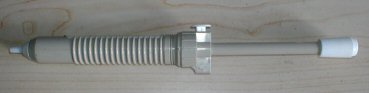
Hi Beethoven, Sorry for making the wrong assumptions. So in your setup you need two Core modules and your own key scanners and to merged them to provide the midi out. I have a similar configuration in that I used two midi keyboards and merged them with MIDIBOX64 to provide a midi out to run the B4. I used the analog inputs for the drawbars and the potentiometers other controls. The switches are for toggle functions. In fact I have tranplanted the two midi keyboards' electronics into my Yamaha E75 organ (which has no midi out) and together with the MIDIBOX64 to play the B4. The original E75 pedals are used for the bass. I find this setup a bit complicated and involved a large chip count. I am attaching a crude block diagram of a full B4 controller for you comments. If a software can be developed for this configuration, it would give a low chip count (ie one board does every thing) and easy to implement. Shum PS Rednas - Thanks for the information, could you also comment on my proposed block diagram for the B4. Thanks B4 controller II.JPG

-
Hi Beethoven, Thank you for responding. May I understand it correctly; you have two keyboards (upper and lower) and without the pedalboard. Am I correct to assume that your CRUMAR organ alreay has midi output ports built into the original electronics, and that you are modifying the electronics to give you the velocity and aftertouch functions? If this was not the case, then you would have to have some kind of keyboard encoder to provide keying for the upper and the lower keyboards. You are using the MIDIBOX64 for the drawbars and perhaps other functions. May I know all in all how many Core modules are you using to achieve your goal. I am new to pic and have no idea how programming is being done. As I mentioned in my posting it would be nice to have only one Core Module together with multiplexing electronics to provide the keying functions for the upper, lower keyboard, the pedalboard and switches for other functions such as rotary speaker on-off etc. Additional analogue multiplexing electronics for the drawbars, volume, rotary speaker slow-fast, etc. I am searching for a simple way to implement full control over the B4 and am very interest in your project. Thank you and with best regards. Shum
-
The Hammond organ has a unique sound. However, it would be a heavy investment to buy one. Selling it under unforeseen circumstances, in my opinion is not easy. The alternative is to use an emulator software B4 developed by Native Instruments. In my opinion, the emulation in both the Tone Wheel sound and effect of the rotary speaker almost resemble the real thing. The Midibox developed by TK makes it easy to configure it as a controller for the B4. However to setup a workable system, beside the controller, many other components are needed, such as the upper and the lower keyboards and the pedalboard. These keyboards got to have a midi interface. A midi merger is also required. To make thing simple, perhaps the Midibox can be morphed into something with the PIC driving four 8 x 8 diode matrix multiplexers. The first second and the third being the key switches for the upper, lower manuals and the pedalboards respectively. The midi channel (1 to 3) for each of the matrix multiplexer should be individual selectable to enable coupling between boards. The fourth being the matrix for toggle switches (with midi learn capability) for the various B4 controller functions. Six 8 to 1 multiplex analogue channels (with midi learn capability) are needed. Three for the upper, lower keyboard and pedalboard drawbars. The rest are for other controller functions of the B4. If the "ONE" PIC full B4 controller is doable, I hope one day my wish will come true.
-
Hi Henrygr, Some years aga I built the midibox16 as a prototype to control the drawbars of B4 (Hammond simulator). The midibox64 using the latest MIOS is, I think approprate for emulating the controls for the B4. I am using such a device just for that. I am nor sure if this information is useful. Regards Shum
-
Hi, I am glad to note that you are progressing well. Wishinh you the best with the the SID module. By the way where did you buy your SID chip from and at what price? Regards Shum
-
Hi, The 5vdc you measured is only the dc supply points to the ICs, however, there is a need to ensure that there are no bridges between tracks, especially between the IC legs. Also make sure that there are no bad or dry solder joins. The pic18F452 is susceptible to high frequency digital noise. Make sure you have the decoupling capacitors inplaced. A good power supply is also needed. When all these are inplaced you can plug in the optocoupler and the pic. If everything is ok, and your pic has a preloaded bootstrap loader, you can upload MIOS and later the application programme. Please read from the following web page if you intend to use the C64 PSU for the core and the SID module. http://www.ucapps.de/mbhp/mbhp_4xsid_c64_psu_optimized.pdf. Shum
-
Well, good for you. So, you can now proceed to remount the 7805 and when it's done and powered up, you should get 5vdc between pins 3 and 2 of the 7805 or at J2. Good luck with the rest of your project. Shum
-
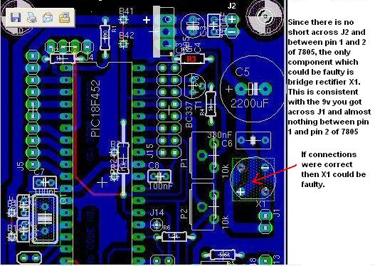
Hi, The reading on (a) is correct, but you need not hold the probes there for more than 5 minutes (few seconds would do). This test was to establish if there were a short. It has not. (b) is to check if the rectifier is ok. In this test you should get some resistance value(not infinity) reading. © shows that J1 terminals are connected to the ~ side of the rectifier, which is correct. All these tests indicated that you do not have a problem with the power circuit of the board. If you apply 9vdc to J1, you should get 9vdc at the + and - terminals of C5 as you have expected it also. I am really puzzled if you are not getting the 9vdc there. Sorry for not being able to help solve your problem if this is the case. Shum Shum
-
Hi docbrown, Glad to be of service. Your are welcome. Good luck with your midibox project. Shum
-
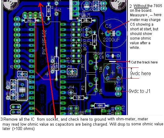
Hi, Let us summarise what had been done so far; (1) No ICs are being mounted on the board except the rectifier. (2) No short circuit between positive rail and ground (measured betweeb + and - points of C5. (3) Rectifier is mounted correctly with the two points marked ~ connected to J1. (4) Applied 9vdc from your psu to J1 and had only 0.9vdc across + and - of C5. Can you confirm what I listed above is correct. Please do two more measurements before you cut the track, (a) Use ohm-meter with its positive lead (red) at + point and negative lead (black) at - point of C5. What is the measured reading. (b) Do same measurement, this time with negative lead (black) at the + point and positive lead (red) at - point of C5. What is the reading. © Do ohmic measurement of J1 with positive lead of meter to one point and negative lead to the other and vice versa. What are the readings. Sorry for asking so many questions, I am trying to help. Shum
-
Hi, I did,nt know that you have already removed the 7805. What about the optocoupler? is it still in the circuit. If you have not cut the track, what would be the reading (resistance), (1) at the + and - points of the C5, (2) between + and - points of C4 (or at J2). The readings need not be exact. If it should turn infinite as you mentioned, then there is no short between 5v and ground. If you had the rectifier in place, and you feed J1 with your PSU (9vdc), then you should get 9vdc between + and - pionts at C5. Can you do this part and le me know the result. As I mentioned, cutting the track and feeding J1 with 9vdc you will get 9vdc between + and - points at the rectifier. Measuring the resistance between + and ground of C5 and C6 is to establish if the was any short before applying power to J1. Shum
-
Hi, Yes, once the the caps are charged you should get infinite resistance. Since you have other components such resistors and IC on the boad you would have some resistance reading (depending on polarity). There is a typo error on the last sentence at the bottom of the photo. It should read "will increase to some ohmic value later" (depending on polarity). Shum
-
Hi, Basically the v2 and v3 boards are the same. Anyway, can't think of anyother ways to help except what I mentioned earlier that you cut the track to check and bridge it back by soldering a piece of wire across the cut track. I am attaching here a photo of the board which I marked the cut. Please follow the instruction written on the photo. Since you have experience with amplifier and other audio stuff, it should be easy for you to do this. Good luck. Let me know how you are progressing. Shum

-
Hi, Really cannot understand why this simple problem cannot be traced. We almost exhausted the steps that could be taken to solve this problem. Unfortunately you don't have a desoldering pump to help removing the components, other wise you could trace the fault by elimination. Is the layout of the pcb you bought similar to that found on Thorsten's site? What I would do in a difficult case is to cut the suspected pcb track so that I can isolate the circuit for testing, and solder it back afterwords. Would you be will to do this, if so I can use Thorsten's pcb layout and mark the place where you can cut the track for testing. Shum
-
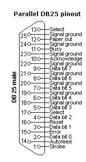
Hi docbrown, Data_out (Acknowledge) is pin 10. Data_in is pin 2. Vdd_enable is pin 4. Vpp_enable is pin 5, and clock is pin 3. Signal ground are from pins 18 to 25. Attached is a pinout of the D25. Hope this will help. Regards Shum

-
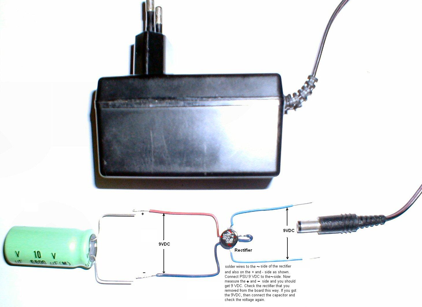
Hi, I see you that you still have not found what was wrong with the board's power supply. Just a suggestion, you have already removed the rectifier from the board and mounted a new one. What you can do to check the rectifier that you removed and connect wires as shown in the attached picture. Connect 9VDC from your PSU to the ~ side of the rectifier and measure the + and - side. You should get 9VDC as well. If this is the case the rectifier is ok. The there might be some other problem with the board. Check this out first and let see the result. Good luck Shum

-
Hi, Perhps a little tip to clear the hole of solder on the soldering pad. Melt the solder on the pad quickly at the same time use a fine tooth pick to poke through the melted solder leaving a clear through hole. Shum
-
Hi, You conntected the psu, and checked the voltage between the + and the - pins of the rectifier and the voltage fluctuates between 1 and 2 volts, it would seem that the rectifier is either connected incorrectly or the rectifier is no good. Try us the AC scale of the multi-meter to measure the + and the - pins of the rectifier again. If you got a higher voltage, then it is connected the wrong way round. Try buy one of the sucking devices shown in the picture in my pervious posting, it will help very much to desolder component from circuit board. Radio shack sells them. Shum
-
Hi, I hope you have some luck with the power supply. I attached there snapshot of the core layout and a cheap device that I use to desolder by sucking out the molten solder. Regards Shum


-
Hi, On the rectifier unit (with 4 leads) two of them are marked (+) and (-) and the other two are not mark or marked as AC. Before you remove the 7805, use your ohm meter to measure the terminals on J2, there should not be a short circuit (zero ohm). I also attached a a drawing to help you troubleshoot. If all things failed, then remove the 7805 and do the measurement again. Hope this will help. Best of luck Shum psu.JPG

-
Hi, The voltage at J1 is where the power supply is connected. In your case you measured 9V. This is ok. You mentioned you got only 0.5v a between pin 1 and pin 2 of the 7805. This seems to me that you may have wired the rectifier X1 incorrectly. Are you using 4 diodes or just unit with 4 leads. Make sure you follow the schematic and wire the diodes correctly. Disconnect pin 1 of the 7805 and with no power applied to J1, use an ohm meter to measure the positive (+) and the negative (-) line, (positive lead of meter red colour) to the (+) side, you should get some reading in k ohms and almost infinity if the leads were reversed. Regards Shum
-
Din and Dout modules with respect to their schematics
Shum posted a topic in Testing/Troubleshooting
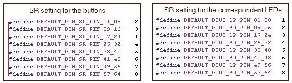
Hi, I would like to seek clarifications on the Din and Dout modules with respect to their relationship regarding button numbering and the correspondent LED numbering. There are 4 shift registers, IC1 to IC4 in each Din and Dout module. I take it that IC1 to IC4 represents shift register 1 to 4. The schematics show the following mapping for the buttons and correspondent LEDs. IC1 - 74HC156 IC1 - 74HC595 pin# button# pin# LED# 11 1 (D0) 15 1 (D0) 12 2 (D1) 1 2 (D1) 13 3 (D2) 2 3 (D2) 14 4 (D3) 3 4 (D3) 3 5 (D4) 4 5 (D4) 4 6 (D5) 5 6 (D5) 5 7 (D6) 6 7 (D6) 6 8 (D7) 7 8 (D7) Have I intrepreting this correctly? The mapping as given in the main.asm file is as shown in the snapshot. I need direction in this respect. Thanks Best regards Shum
-
Hi Stryd_One, I shall send you the document on my experience in building the midibox, once I finished it. Need your mail address. Thanks. Best regards Shum
-
Hi Stryd_one, I had a look at the wiki syntax and the rest of the stuff at the playground, sorry I do not understand all the stuff there. Anyway I have done some work with MS Frontpage. Would it be possible to document what I have done on the LCD in Frontpage and upload it to the web? Thanks Regards Shum
-
Hi Stryd_one, Yes, how do I go about doing it? Regards Shum