lylehaze
-
Posts
613 -
Joined
-
Last visited
Content Type
Profiles
Forums
Blogs
Gallery
Everything posted by lylehaze
-
Yes, it's best to split them after the input buffers. Just take the buffer output to both PGA inputs. In my PM I asked about what your plans were, that was before I read this thread. I see this now. Looks like fun! LyleHaze
-
Much Better! It took me a minute to see the resistors along the SDO/SDA path, but they are there on end. The extra capacitors will really help keep the audio quiet. Looks great! Can I order one now? You mentioned X4 going to X8. That's a lot of channels. The X4 you have now will do basic volume and balance/pan for eight pairs of Audio. Or level only for 16 Mono channels. What you're showing right now (X4) is enough for my project. Of course, if you do make a bigger board, people could just mount as many chips as they need and leave the rest empty. A great way to start my day. Now it's off to shovel snow and get to work. LyleHaze
-
Well, better late than never. I just checked, and each input on a DINX4 board is pulled up to five volts by a 10K Ohm resistor. So the current would be 5 / 10000 = 0.0005 Amps This would more commonly be called 0.5 ma (milli-amps). Since there are 32 inputs on a DINX4, this means we might draw as much as 16 ma just for the pullup resistors (if all were grounded at once). All estimates are only as close as your resistor tolerance and your power supply voltage tolerance. Have Fun, LyleHaze
-
Yes, of course you can add it to the WIKI! Also, the PGA chips have a range from +31.5dB to -95.5dB in 0.5 dB steps, so that's actually 255 separate levels plus MUTE. Since I'm using CC7 for control, I only have 127 active levels (plus MUTE), but the additional resolution is used by the LOG conversion for smoother final resolution. I hope that helps, LyleHaze
-
Wow, Looks great! I have been trying to get around to doing a board layout in Eagle, but there's never enough time. If I can make a few suggestions: There should be pull-down resistors between each SDO and SDI pin.. and there should be about four capacitors for each PGA chip. I can send the datasheet with that stuff shown if you want it. If you are having boards made, PLEASE let me know. I'd love to have a couple made for me too, if I can afford them. Yes, you can add this board to the WIKI if you want. Maybe we should wait until we have one built and working. Thank You, LyleHaze
-
Yes. mono controls would be a simple change. Right now the table of stereo settings (volume and balance) are read and converted to a table of 32 monophonic levels. These are then changed from linear to log and then they get sent out. You could simply maintain the 32 levels directly and everything would work, with or without the log conversion. For scenes, Pilo has written a single frame snapshot routine that could easily be extended. I'm not using it but the code is included. For panning a mono signal into a stereo pair, it would be easiest to feed the signal into the stereo design and just use the balance/pan control for position. LyleHaze
-
I'm glad the mixer looks interesting. It's been in use daily since it was first released here. You asked about using Motorfaders AND PGA chips. Yes, I suppose you can, but usually (if I understand you right) you would use one or the other.. Motorfaders alone can do volume control without PGA chips. The reason I went with the PGA chips is that there are no moving parts, and no pots or switches to get dirty over time. So the performance should be just as quiet in ten years as it is today. As far as sequencing a mix, yes, absolutely! The current software provides for up to sixteen stereo pairs, handling volume and pan for each pair. Of course you can change this, but I wanted it to match the sixteen channels of MIDI, so I went with the more obvious route. I can currently mix from a board of encoders and from my sequencer and use presets from a script file, all active at all times. It's really handy to type "mute" into a command shell and have all the audio drop out instantly. Zipper noise? Yes, I've heard it under some extreme conditions, but it's not a big problem unless your final amp gain is set way too high. (which may be normal for some people ;-) ) The PGA chips have a zero-crossing option built in. Anyway, yes, the board still works, and sounds pretty darn good, too. If I can be any help, just ask. LyleHaze
-

Advice needed: Should I buy first or do some more research?
lylehaze replied to banjobater's topic in Design Concepts
It STILL sounds like fun.. Yes, unless you'll be needing multiple MIDI ports (which I don't think you will) then a "standard" core should be fine. LCD would be invaluable, bunch of LED's off the DOUT, probably mounted in the shape of a neck full of frets, just to visualize the results.Remember each LED gets a resistor. BUT.. I'm not a MIDIBox expert.. I'm a bit of a newbie myself. And I am a complete zero when it comes to banjos. Nothing to fret about though. Just pick your way through the information on this site. Have Fun, LyleHaze -
Advice needed: Should I buy first or do some more research?
lylehaze replied to banjobater's topic in Design Concepts
Sounds like a fun project. If I were doing the same project, I would use a MIDIBox. The fact that MIOS is already written and stable really makes the project much more reachable. Something to think about.. MIDI gives a number for each note, but no clue as to which string to fret/pluck. Obviously many notes have more than one possible fret/string combination. One possible solution: use a different channel for each string. OK, so you probably knew that already.. Yes, starting with LEDs on the outputs will let you see what you're doing. Then adding relays will let you drive more current. In that light, maybe the "Midification" forum would be useful for you to browse. In any case, have fun! LyleHaze -
It's not hard to convert log to linear (or linear to log) in software, although there is a loss in resolution. Whether or not it's "acceptable" depends on the application and the user. LyleHaze
-
a floorboard for my amp.Help would be appreciated!
lylehaze replied to Maurizio's topic in Design Concepts
OK, I'll try. First, WELCOME! I hope you have fun here. What I'll suggest is just one way to go, there are many people here, and some will want to do this differently. The floorboard code is written for an older PIC 16 that we don't use much anymore. Most new projects are written for one of the 18F chips that we have available. So, if you want to use that older code, you'll have to learn a bit of ASM to make the changes. If you get a new MIDIBox core, it'll come with MIOS already installed, and you'll be ready to play. Since you speak C already, I think you'll find it easier to just start from scratch. To get some idea what I'm talking about, start with http://www.midibox.org/dokuwiki/doku.php?id=application_development and have a good read. If it looks interesting, try: http://www.ucapps.de/mios_c.html especially the table at the end. Finally, once you want to see more of the insides of MIOS, look this over: http://www.ucapps.de/cmios_fun.html You can see now that It's not hard to connect inputs (like floorboard switches) with outputs (like sending program changes and lighting LEDs). You can really just describe what you want in C, compile it, and download it to the floorboard without even unplugging it. The bootloader makes everything very convenient. Start with the reading I showed you. If you think it looks like fun, download the source to some other projects that are written in C, and have a look around. I think you'll find it's not too difficult at all. Most important, HAVE FUN! LyleHaze -
a midi-in connector for pc... with no components.
lylehaze replied to jon_oz's topic in Design Concepts
It's a bit more complicated than you think. USB is a serial BUS, not a serial port. That means that there is more going through it than just a stream of data. The lower levels require "negotiations" between the host (usually your PC) and the device. Your device must recognize and respond to questions from the host. It must identify itself with some combination of manufacturer, name, serial number, device class, device subclass, power requirements, and whether it it taking it's power from the USB port or if it brought it's own. If you can't get past all of the above, the OS (windows,OSX,OS4, whatever) won't even make the device available for applications like your program. Assuming you've made it that far, information will then need to be received and organized into packets, formatted according to the USB spec. I can provide a link to that document if you're still interested. :-) Now, I'm not the kind of guy that likes to squash other peoples dreams, but if you can handle what I've described above with nothing more than an optocoupler, friend, you can go FAR in this business. We have discussed before on this board that you might use an FTDI USB to Serial chip, hack the baud rate settings to get 31250 (yes, it can do that), and then use the Yamaha ToHost drivers to connect MIDI devices to this "virtual" serial port. All possible, if not tested yet.. But you are still spending as much as you would on a USB MIDI adapter. Just my two cents, but unless the challenge is the reward, your time would be better spent making music. Whatever you do, Have Fun, LyleHaze "Always have a song in your heart. It's like Karaoke for the voices in your head." -
James. Wow, I'm late. I've been away. I understand that C is preferred, but I do have a horizonital bar display written in asm. It's also stereo, offering separate left and right bars "growing" out from the middle. I don't know if all HD44780 displays have the same special characters, but if you'd like to check it out anyway, just grab the code for MBMixer and look in the user_LCD file, I think. I tried to comment a bit heavy, to break down each step of the code. As it is written now, it uses all of the bottom line of a 2X20 VFD. Maybe you'll find something useful in it. Lyle http://www.midibox.org/dokuwiki/doku.php?do=show&id=midiboxmixer
-
I don't understand.. Not the first time that has happened. Normally, all voltages are measured from "Ground". So how can you possibly have 13 volts from Ground to Ground? Please set your meter to read DC volts, 20 volt scale. Connect the black lead to the metal tab of the 7805 voltage regulator. Carefully touch the red lead to the first and last pins of the 7805, tell us what each of those are reading. These clues will give us a starting place. Have Fun, LyleHaze
-
Sorry I'm late, I've been out of town. Very nice design, I have a few comments, if I may: I see no problem with the grounding arrangement at all. The difference is correct, as the difference between a Single supply and a bipolar one. Heatsinks: All of the positive regulators (78xx) have their center tabs grounded, so no problem mounting them directly to the grounded metal case. do NOT do this with the negative regulator. Use a dab of thermal grease for better heat conduction. There may be a problem between the +12 output and the 9 volt regulator. Having 2200 uf on the LOAD side of the 7812 may cause a problem when powering down. It may briefly have a higher voltage on the output of the 7812 than on the input. This is not good for the regulator. 2 possible solutions: 1> place a diode across the 7812, cathode to input, anode to output. this will conduct only when output voltage is above input voltage. 2> supply the 7809 from the same V+ as the 7812, instead of feeding it regulated 12 Volts. Yes, the 7809 will get a little hotter, and the 7812 will stay a little cooler. Personally, I prefer the second solution. In any case, nice design! Have Fun, LyleHaze
-
Years ago, on a computer called "Amiga", there was an application called "SuperJam" that allowed non-musical types to compose freeform, and musical types could even excel at it easily. The Author was "Todor Fay", who was later bought out and hired by a company called "Microsoft". He then led the team that created "Direct Music", a subset of "Direct X". I recall that there was even an application that ran on windows that would allow improvisational composition. The software was buried somewhere on a DirectX 9 install CD, I believe. Could be worth looking for. The primary target was to allow game makers to create copyright-free musical scores for their games. Now back to the fun stuff. If you want to let "Joe average" do interactive composition... Could you do it from a "Wiimote controller"?? Could be a real hit, both figuratively and literally. Just dreaming, LyleHaze :-)
-
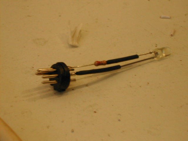
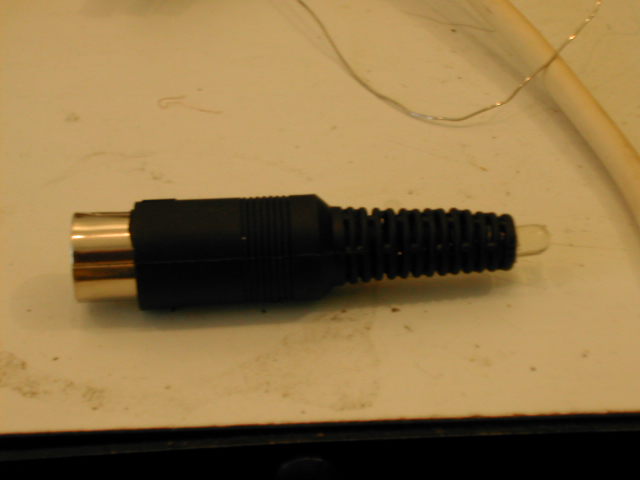
I believe that is symptomatic of a working core. But I might be mistaken. ;) Confirmed: You have MIOS already installed! See: http://www.ucapps.de/mios_bootstrap_newbies.html for more details. Not long ago, PICs were shipped with a bootloader, and you loaded MIOS, then loaded your application. recently, Smash started shipping with MIOS installed. I think "Bootload only" would keep repeating the upload request, but MIOS may only issue it once. I would try loading your application with MIOS studio. You may be ready to rock. re: MIDI activity monitor: I soldered up a DIN plug, 220 Ohm resistor, and a spare LED, and it provides a pretty good indicator. Yes, if you are only getting a few messages, it only flickers faintly, but definetly good enough to see. More MIDI traffic results in brighter flickering. See Attached pictures The "Flat Side" of the LED is on the resistor side in this pic. Cool toy for testing, about as cheap as it could be. Good luck with your MIDIBox, let us know how it goes! LyleHaze


-
Hi, I'm back, for a few minutes anyway. re:Pin25. Your meter is probably not fast enough to see brief transmissions on pin 25. Good thought though. Got a spare LED? 220 Ohm resistor? 5 pin DIN plug? I wonder if a MIDI activity monitor could be that easy? I'll have to try that one day. re: "Verify of ICProg" That would be if you burned your own PIC. Since you didn't, you'll have to trust that Smash got it right. I'd call that a pretty safe bet. If all your voltages are good, and the crystal and it's caps are good, and the MIDI OUT circuit is good ( two reisitors?) there's not much else I think. As long as you didn't plug the PIC in backwards.. ::) Gotta go, I'll check in later LyleHaze
-
Party on, Dude! LyleHaze
-
I have never seen a 7805 with an isolated tab. Weird! but the voltages sound good, at the 7805, at least. I have something that will keep me busy, I'll be back in an hour or two. Family comes first. LyleHaze
-
Interesting.. OK, when reading across the rectifier, you show 10.62 from + to -.. That looks good. BUT!! the - of the rectifier should be connected to the tab of the 7805, (also the middle pin) and the + of the rectifier should be connected to pin 1 of the 7805 (the pin furthest from the MIDI sockets). Yes, there's a capacitor in between, but unless you got that in backwards, it shouldn't be a problem. and even if you did.. well, there's a connection problem here. Make sure that the rectifier has the + in the correct place. The 4 pins of the rectifier: one is marked +, and should go across 2 caps and to the bottom pin of the 7805. one is marked - , and should go to the middle pin of the 7805 2 are marked ~, and should each go to one pin of j1. Let us know how it goes. LyleHaze
-
Hey, at least I was nice enough to warn him! ;D LyleHaze
-
It's normal for unregulated power supplies to output a higher voltage when not loaded. Try this please: set your meter to DC VOLTS connect the black lead to the tab of the 7805 regulator carefully touch the red lead to the first pin of the 7805, tell me the voltage. carefully touch the red lead to the last leg of the 7805. again, tell me the voltage. finally, is the metal tab of the 7805 hot? watch your fingers. LyleHaze
-
MIOS Studio can't find my USB MIDI Device
lylehaze replied to napierzaza's topic in MIDIbox Tools & MIOS Studio
They appear to be identical, at least in appearance. The package clearly states "Class Compliant" on the later ones that work with the built in drivers. Another way to tell is to check the Class and Subclass numbers.. Class compliant MIDI interfaces are Class 1 (Audio) Subclass 3 (MIDI) But unless you are running OS4 I won't be able to tell you which tools to check that with. Have Fun, LyleHaze -
Has anyone tried using a stepper motor as an encoder.
lylehaze replied to Nitrus's topic in Parts Questions
Interesting, but a lot of work (and parts) for an encoder that won't track slowly. The encoders at SmashTVs site are a bit more affordable! Cool though. LyleHaze