

e-toy
-
Posts
32 -
Joined
-
Last visited
Never
Content Type
Profiles
Forums
Blogs
Gallery
Posts posted by e-toy
-
-
just seen some videos about the tenori-on on youtube ...
would be really crazy to have a MB-SEQ with a 16 x 16 LED button UI 8)
-
well, I have read a lot of threads about PWM and stepper motors and so on, but I couldnt find an final answer that helps me to answer my next question.
I like to control some RC servos with the MB64. That means the DOUT have to output an PWM signal.
I'ts not really highspeed clocked ... every 20ms a pulse of 1ms (min. value) to 2 ms (max.value).
I have read that PWM needs very much performance, but I dont know if this relative slow PWM is also too much for an PIC (in the case that there are 4 to 16 such PWM needet). And finaly I have no idea how I could programm such a PWM "option" ::).
someone tried this ?
any hints ?
Thanks
e-toy
-
Hey neb, you ever considered just disconnecting power to the fuser?
Most printers wont work if you only disconnect the fuser power. There's an thermal sensor wich controls the heat and if the heat dont come, the printer will report an error. If you can hack the sensor control, it will work.
-
Thanks for all your tips !
If I understand right, I could attach an RS-485/422 line driver directly to the MIDI Ports to transmit MIDI over longer distance. There are no special Driver needet. right ?
The RS-485 multi-point feature sound very nice :)
Do I have to use a full duplex line (2 Twisted pair) or does it work also work with half duplex ?
I will try to explane what project I'm working on. May it help ;)
I need to control some Simple I/O's distributed on an wide space (outdoor). The I/O should have 16 Outputs and 16 Inputs. Every Output switch an Relais. The Input monitors the Output load (is a consumer e.g. lamp, attached proper to the Relais or not) and make it visible with an LED on the I/O.
Every I/O should be adressed separatly (may I could use MIDI channels for a max of 15 I/O's).
I would use one Core and 4DOUT + 2DIN Module for One I/O
I also need a "Remote Control" to switch these Output's on an off. Normal state should be off, after trigger the Output, it should go in ON state (for 10 - 100 ms). The Output load state should be visible also on the "Remote Control".
For the "remote control" I would use one core and x DIN/DOUT modules (depends on how much Buttons/Leds would be implemented. I think the MB64 SW could also be usable insted of the MIDIO128
because (if it works) I may also would try to implement AIN on the "Remote Control" and AOUT on the I/O Module.
So i think the only problem is to transmit the MIDI data over long distance.
I know, my english is not very perfect, but I hope you understand what I try to explane.
e-toy
-
ok
thanks for your infos TK
I think I'm not the dedicated freak to solve the Can implementation ::)
what about RS422 ?
Do you mean instead of the MAX232 an other driver or an RS232 to RS422
converter ?
The only problem with RS232/422 is (as far as i know) the unicast.
So I can only connect two devices together ???
And of course the cables (two twisted pairs for RS422)
hmm
I'm a bit confused
e-toy
-
a pair of those midi over ethernet boxes
quiet expensive (over 400 bucks) for one pair, or ceaper boxes dont reach enought distance ...
maybe theres a good cheap box, but I could't found it.
May there's a much cheaper solution ::) what about max distance for DIN/DOUT Signals ?
-
have found some answers
Do I need extra CAN tranceivers ?Yes
What is needet for longer distance ?Two wire solution (differential)
-
hi there
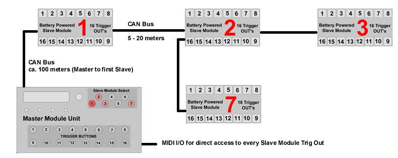
I'm on an project for an MIDIO 128 like controller, but I need very long distances between DIN and DOUT (up to 200 meters total) . As I know that the new PIC 18F4685 use an ECAN Bus for linking to slave core Modules and this ECAN are capable to transport Data over long Distances( 40 meters @ 1Mb/sec), I asked myself if I also could use such a PIC for MIDIO 128.
Well, I didnt found an answer :( so I try it here ;)
My idea is to use a Master Unit Controller wich I can select the Slave Modules and trig the DOUT of the selected Slave Module. In addition I use an MIDI I/O to control every DOUT of every attached slave in realtime. The Slave Modules would be linked with Master over the CAN Bus (long distance)
As I'm not an expert in MIOS and C programming (in fact currently I'm an beginner) I have a few questions
1. I think MIOS 1.9 is ported to PIC18F4685 and CAN BUS is accesible.
Is MIDIO128 also usable on this PIC and can access to the CAN Bus also ?
Is MIDIO128 suitable for my project ?
Better ways ?
2. Is it possible in MIOS to reduce the Can Bus speed so i can use longer wires (distance to Slave) ?
Do I need extra CAN tranceivers ?
3. In MBSID CAN it's a onewire solution. What is needet for longer distance ?
The slave Modules are Battery Powered. Is a common ground imortant ?
May someone can give me a hint ?
Thanks in advance
e-toy
Have made a picture for better visualisation

-
ok
I found it ;)
sorry for wasting time ::)
for all others who couldn't found it
-
I don't find any description about connection of the second SID Board on J14
me too
-
go ahead and try ;)
for me graphics arn't really important, as I only need it for music purpose.
But you could easy make a simple hack to toggle between Gaming tune and Music tune. Just use two pots an a switch to toggle between the two different values.
Or even easier. Buy an NTSC Console! (and hope that your'e TV is able to display NTSC Video)
If someone knows an other working hack that alter the tune of sound without change the video frequency, let me know ;)
-
hey Martin_Dubka
let me guess
You are using a MIDINES in an European NES Console
right ;)
look at here
-
vielleicht ein zu klein dimensioniertes Netzteil ? ::)
-
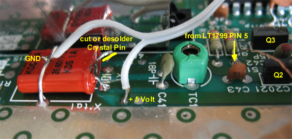
i had to reopen my NES to make a picture
With the pot on PIN 3 of LT1799 you can adjust the CPU clock frequency (tune)
right tune will be at arround 3,8K so you can use a 5k or 10k pot.
cables should be as short as possible. CPU clock frequency is about 28 Mhz.
Note that you wont get a picture out of the console anymore because the GPU will also be "tuned" and
TV cant sync anymore to this frequency.
greets
e-toy


-
like vedge said
this was, for me the shortest path for the NES, both finance, and time wise.that's absolutley right. even if 90$ + seems to be lot of money, you will need much more (particularly time)to develop a new system based on MIOS.
In the meantime i found a solution to "tune" my PAL NES :)
I used an LT1799 Frequency generator as Crystal substitution for the CPU clock. Now I can tune my console in a wide range.
greets
e-toy
-
heya leaphion
the sid itself have a multimode filter, but if you want to use an external hp filter may check out the Korg sallen-key design. it was ben used on various Korg Synths (like the MS series and Mono/Poly)
this filter can be configured as HP or LP and have normally 12dB/okt.
-
as i am still planning to make a step c cs for my sid, I'm not shure how it will looks like.
I have a tabletop case at home that i like to use but it's a bit to small for a regular cs
so i have to decide if i make something like the "little surface, maximum control" from Ixox,
or something radical reduced.
In the case of the "little surface, maximum control" design I would like to add the mod matrix, but
as i dont have as much space in the case i would like to make it with illuminated (tact) switches.
this means that i have to make a switch (scan?) matrix. with this style variant i save the space for the regular switches.
so my question: is a scan matrix + a LED matrix supported in MB sid ?
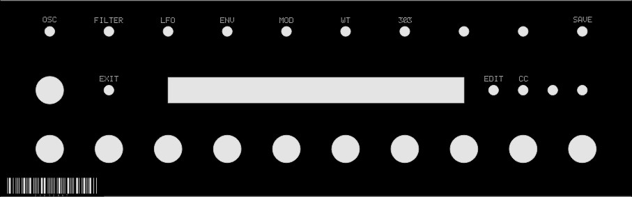
the other design is more a "fast MENU access" control syle.
It consist of a 2x40 display and for every parameter shown in the display there is a Rotary Encoder.
+ fast access buttons for the Menu.
The point is, if you have to scroll thru the Menu (i.e. to reach the PW in OSC Menu) of course the
encoders have to be reassignd to actual shown parameters.
Could this work ?
I added a pic of the "fast Menu access" cs

-
I have schematics for the Juno. Unfortunatley only for the Juno 6 (no DCB) and the Juno 106 (MIDIfied)
The Juno is one of my alltime favorite Synth, I had also a Juno 60 but it was to expensive to MIDIfy so I bougth an Juno 106 wich is very well MIDI controllable.
I think the Kenton box is the cheapest way for MIDI control. But The Kenton DCB can only provide Note ON/OFF and Programm change. Parameter control over MIDI is not possible with Kenton. So If you would like to have Juno 106 like control even with DIY you will spend much more then a used Juno 106 cost.
btw. If you would sell it, Im your man ::)
e-toy
-
Netter Encoder, nur leider ein bischen sehr teuer.
Das ist ein Optischer Encoder, d.h. der ist aktiv b.z.w. der hat schon elektronik drin. Somit braucht der auch eine Betriebsspannung von 5 Volt und eine Masse verbindung. Auf Kanal A und Kanal B gibt er dann einen Puls Signal aus welches direkt an den 74HC165 angeschlossen werden kann. Die pulldown Wiederstände sollten somit eigentlich nicht mehr nötig sein.
-
As I am planing to make a Filter extension for my MidiBox SID, I have a few question about the use of AOUT_LC in the MIDibox SID project.
I like to have a small (2 channel) AOUT module like the AOUT_LC, but I'm not really happy with the fact that Filter resonance will only have 4 bit (16 steps), so my question regards mostly this problem.
Since I read that the Filter cutoff parameter of the SID SW can be interpolated, I think Filter resonance will still have max 128 steps (no interpolation). Right ?
How much steps (or in other words, bits) have the smoothed cutoff signal ?
Currently 12/4 Bit is the only supported output format of the AOUT_LC (for MB_SID). But it seems that theoretical all combinations of max 16 bit could be possible (eg. 9/7 bit). Right ?
Is it just a matter of HW configuration and the driver ?
Wich CV format will the AOUT_LC (controlled by the SID SW) provide ? V/Oct or Hz/V ?
e-toy
-
naja, das datenblatt hätt ich ja schon gerne vor dem kauf gesehen...
wenn's eins mit negativer kontrastspannung ist, wird's aufwändiger mit dem netzteil :-\
-
@seppoman
Danke 8)
genau so eins hab ich gesucht !
Wieviel strom zieht das Teil ?
-
thank you guys for discussing
I'm a noob in digital electronis, but I like to learn to understand it.
@seppoman
your project is very interesting as cheap alternative to the AOUT (8 channels)
I'm looking forward and hope you will find the time to realize this project.
@ MyCo
You're right. But this is nearly the same as the AOUT_LC. Exept that you change the resistor ladder with the DAC. It shurley looks better, may it's easier to build and hopefully works more precise then the AOUT_LC version.
Did you have made such a AOUT module ? What about the driver (and schematic) ? :)
@all
what's the benefit of 12 bit DAC's for CV controlled By CC (7 Bit) ?
I think there should be a interpolation of CC data (SW) to obtain a finer stepping of CV,
or the CV will allways have only 127 steps independent if you use a 8 bit or 12 bit DAC.
or am I wrong ?
e-toy
-
I also have searched houres to find a new DAC type, without a real hit.
no usable DAC with Serial input, nor Parallel.
but, what about a I²C DAC ?
maybe like the DAC7574 or LTC2625 ? Not the best technical spec, but maybe better to implement ?
e-toy


ever heard about faked SID chips ?
in Miscellaneous
Posted
http://kevtris.org/Projects/sid/remarked_sids.html
well, I wonder if someone have made such experience with "old new stock" chips ?
may it's a common 6581 problem with dead voices and filters, but what about a faked print on the chip?
quiet a bit much work to fake such a chip just to sell it as "new"...