vedge
-
Posts
60 -
Joined
-
Last visited
Never
Content Type
Profiles
Forums
Blogs
Gallery
Everything posted by vedge
-
fried my B40 bridge rectifier following official FM psu PDF
vedge replied to vedge's topic in MIDIbox FM
IT WORKS! more explanations later but i changed the design of my PSU, and i was able to recycle the two psus i made. Now .. too much fun playing with it... well Ok one channel doesn't work, but that doesnt stop me from having fun right now ;) -
fried my B40 bridge rectifier following official FM psu PDF
vedge replied to vedge's topic in MIDIbox FM
Thank you VERY much for looking at my pictures! I didnt expect anyone taking the time to look at them. i didnt dare to connect any psu to the MBHP_OLP3 yet. i want to make sure its running fine first dont want to risk to fry the board. As i said the voltages look fine with a multimeter at the output stage of the the psu, but the transfo either buzzes and overheats or (the other one, just makes the 2A fuses blow) Between the final +12 and ground i get 35K ohm and between the final -12 and ground i get 16K Ohm Is that due to the different 2200 uF caps i have? (one 35v and one 50v) Do you have explicit points and the typical resistance i should get? Also are we sure that what i connect to my 3 input pins are the 3 cables of the "center tap 12,0,12" transfo, in that same order? -
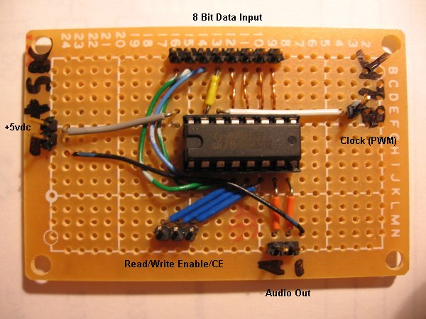
Heres my proto picture. Anyone could build this, just a core, no extra psu. Photos with the core and LCD when i finish that MBFM :)
-
fried my B40 bridge rectifier following official FM psu PDF
vedge replied to vedge's topic in MIDIbox FM
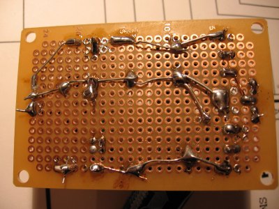
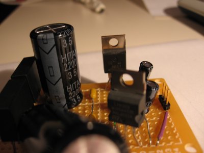
That was the first thing i did :) it had +5VDC and +10VDC ... looked everywhere for a bidirectional. Also, just checked Talion's pdf with yours, and it seems to match up. But, back to my story. just before the fuse blown , i tried with one 12,0,12 1Amp transformer which buzzed like MAD, but quick readouts at the end gave me proper and stable +12/-12 ... but it smelled burned, and the plastic on the transormator melted a bit. So changed the transfo for my previous 2amp one, and that burned the 2amp fuse. I dont know if having the digital potentiometer attached all the time at the end of the chain could have caused the overheat? So there must be something wrongish in my board, but not enough to cause bad results at the end of the chain. I know about the pinout of the 7912, the polarity of the electrolytics... im so desperate i think im going to show my museum of horrors. dont worry about the 2nd 2200 cap thats sideways, that was on purpose so that the thing could fit in a 1U rack space (that one was higher than the other) Please report any mal practice, any thing i might be doing wrong. this is entirely self taught. and i accept criticism. For a more "aesthetically pleasing" picture, try this: http://www.midibox.org/forum/index.php?topic=8026.0 -
fried my B40 bridge rectifier following official FM psu PDF
vedge replied to vedge's topic in MIDIbox FM
argh Second PSU, no luck... it just killed my 2A fuse i had in the 120VAC land \ is there an error on the pdf?? Ive done 3 midiboxes, one SN76489AN daughter board, which works, and another psu, but i cant for the life of me finish this. because of that choice of opamp, ill have to throw my MBFM project in the dumpster is there any other opamp i can use? Dont want to be a pain, but this requirement for +-12 VDC is beyond me. I mean i cant even hear the supposedly obvious background noise on the first sound demos of the MBFM! Also why on this thing: http://www.generalguitargadgets.com/pdf/ggg_bipolar_ps.pdf Doesnt it require a "3" cable transo? Seems any 2 cable transfo would do. I can program efficient multithreaded modular synth plugins and hosts but i cant do a simple "real life" bipolar PSU... you have to understand my frustration :) -
fried my B40 bridge rectifier following official FM psu PDF
vedge replied to vedge's topic in MIDIbox FM
So 2 fuses then? On each 12VAC -
fried my B40 bridge rectifier following official FM psu PDF
vedge replied to vedge's topic in MIDIbox FM
Thanks for the explanation TK. Well, i just got back from the store with components to make another one. (im not exaclty sure what is still alive in my old one) Im always reclycling old 1U rack units for my projects, and all of them have fuses tied to the AC three-prong connector. (and it blew last time) Should i add another fuse after the tranfo too? (in the 12VAC area?) -
fried my B40 bridge rectifier following official FM psu PDF
vedge replied to vedge's topic in MIDIbox FM
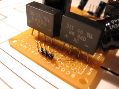
Hello I know both ~'s of a bridge goes to AC. (and they are hooked this way) my question is when you got two bridges for the MBFM, and a center tap power supply, should the same ~ of each bridge go to the center tap? or one or the other ~ of a bridge can connect to it. It is also possble the guy who sold it to me didnt have a clue about the pinout. he said "longest is +, the one in diagonal to + is - and the other two are ~" -
Oh ok. I never really caught on with any sort of DIY cable conenctors like that (same with telephone or 10base-T), i guess i should try .. Thanks
-
Hi, yeah, smells burning here! ok heres the deal, the only dual 12VAC transformer that i found was a 2.0A one (see photo). Is that PSU too much for my poor bridge rectifiers to handle? or i surely hooked something wrong? Is there any logic for hooking up the four ~'s ? should the center cable go to the same ~ from both bridges or it doesnt matter? Just trying to figure out where it got wrong...
-
Hello Theres no mention anywhere that i can find for the cables that tie to sil headers. Frankly ive gone out of old PC motherboards cables.. Is there anyplace that sells these in bulk, say female to female 1 to 2 feet long in various combinations (1, 2, 4, 5 ,8 ,10 pins )?? is there a real name for them "SIL HEADER CABLES" doesnt return lots of hits on google. Cheers
-
Its the right chip alright :) But i dont think the SMS has that chip directly: See: http://www.smspower.org/maxim/docs/SN76489.txt "2. SN76489 sightings ==================== The SN76489AN discrete chip is used in Sega's SG-1000 Mark I and II, and SC-3000 machines. I do not know if the Mark III has a discrete chip or not. The Sega Master System and Game Gear have it integrated into their VDP chips, for backward compatibility to varying extents." The SMS also has a Yamaha YM2413 which i dont have, and frankly, idd be ok with my MBFM once i get that PSU done. But the SMS is not the console i had in mind, its the ColecoVision that i wanted to MIDIfy :) So that "hacked_emulator.mp3" was made using a modified ColEm ColecoVision emulator (http://fms.komkon.org/ColEm/) which sends MIDI CCs to my MIDIBox'ed SN76489AN instead of generating the sounds itself. The game is "PepperII" That site doesnt have the open source version of the SMS emu, so i couldnt test some SMS roms with it :( Ill continue work on it once my MBFM is done. There is a dude on ebay who sells truckloads of these chipps, but minimum order is 25. so ive got, lets say around 20 left.
-
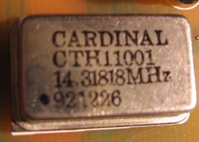
The second osc comes from a new-old stock surplus store, and it had a packaging which i sadly lost. as far as Mhz are concerned, the YMF262.PDF just says "14.32 Mhz". I haven't checked the programming code if there are tables made according to a "wanted frequency", or if the frequency is defined as a variable from the PIC to the YMF, and the YMF assumes the clock to be something fixed. Im at the point where i only need to do a friggin +-12vdc supply. I tested the 5vdc voltages everywhere and they were fine, (this is using the Cardinal Osc) ... so does that mean the crystal is ok for the job? In other words, in order for the YAC's to output 5vdc signals out , does it need to be clocked?
-
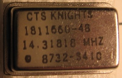
Some unfinished (but working) 80s video game sound chip MIDIBox, that will stay nameless until finished. http://www.midibox.org/forum/index.php?topic=8026.0 Really im just waiting for someone to recognise the tune in that "hacked_emulator.mp3" :) Ive modified an open source emulator to send specially constructed MIDI CC to my board, directly accessing the registers without much translation. Im a programmer, and frankly the electronic nomenclature is to me a huge bunch of random numbers, there are some standards, for caps numbers and resistor colors, but for other components? These are the two "whatever you call 'em" ... is one of them suitable for this? Can anyone guess with the picture? These are four pins alright. the "cardinal" one was on a "Media vision PROAUDIO 3D", which had a YAC and a YMF. The CTS Knight one, well i lost the packaging..
-
Hello Again im the clueless of the bunch here. Ive found a 14.318 crystal with the right form factor named "CTS KNIGHT", is that A TTL ? are there TTL and CMOS crystals? what are the chances its not the right thing? I also could salvage a 14.318 from one of the many SB clone cards containing the YMF/YAC's that i found, one would think with certainty that THAT one would do the trick right? There are soo many unknowns in my MBFM.. i made 2 SIDs and one Secret Chip midiBox, but the leads are so small everywhere on that PCB, and parts have been gathered in many places, so i can only pray that its going to do anything once powered...
-
tried that as well. voltages were wacky on the other PCs
-
I can't believe it! I tried JDM with ALL old my PCs as told. pentium1 200MMX runninng win98SE ->NOGO pentium2 400 running win95 OSR2.5 -> NOGO pentium3 733 running win98se ->NOGO what the hell, about to throw the JDM in the dumpster. Then just for fun, lets try that in my main machine: AthlonX2 ASUS A8N-E NFORCE4's on board COM ports ... TADA!!!! fixed my PIC! Heck you wouldnt believe the LENGHT of that 9 pin cable i used too! must make 15 feet. Theres a ghost in the JDM desing... but lucky me i found ONE that works. So maybe replace "might not work on older computers" by "use PIC burner, or play the lotery with JDM." Now ill never win the million!
-
Just important to note that systendo is a bare synthedit plugin, using synthedit's built in Square and Triangle oscillators, which in most probablility dont have the same caracteristics as the ones in the NES hardware. That depends how anal you are about those thigns :)
-
Its especially agressive since this example was made when the clock was at 2 Mhz, allowing for lower pitches than the normal 3579545 (NTSC) or 3546893 (PAL) , but its not a Pokey, i have no cash these days for more chips, but i plan to. (i want MIDI boxes for all classic console's chips) I guess the attachment is a giver. (slightly out of tune since the PWM runs at 3.33 MHz vs 3.579545 Mhz - original console) Thats very cool, you can look at the NES topic again for an inside pic of my rack. The hardest thing for me was the initial "electronics" learning curve and the PIC/MIDIBox C compiler setup, once i was able to read and write digital bits, It was a walk in the park. And im sure its the same with many old chips, if you just want the bare sounds out, (maybe a few arps) and not do something as extensive as the SID and FM midiboxes. But I do have lots of questions about electronics left. TTL/CMOS logic voltage differences amonsgt other thigns hacked_emulator.mp3
-
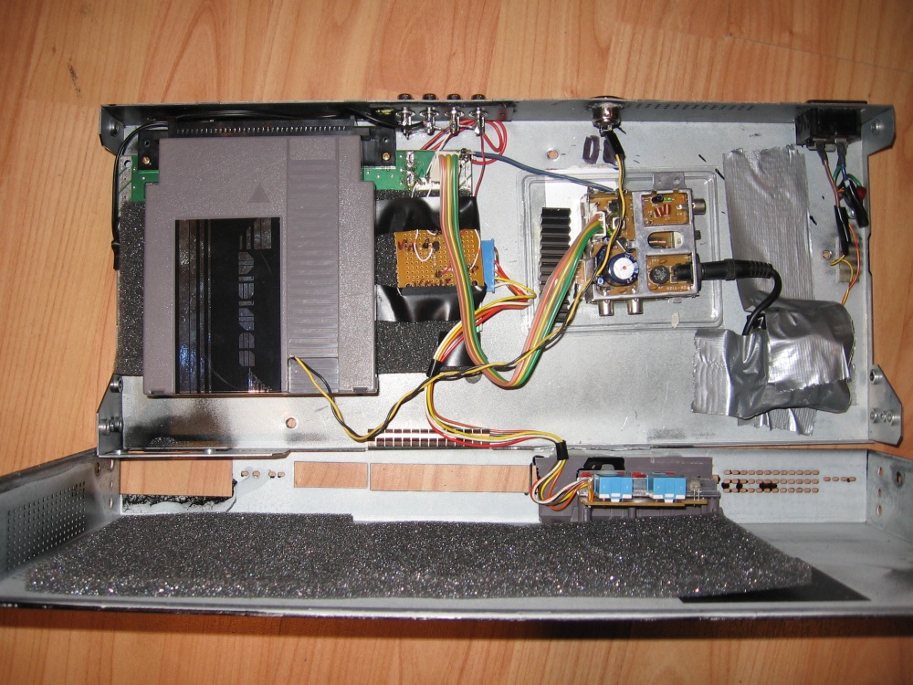
Oh, thats very sad indeed. the tables are hardcoded with the NTSC pulse lenghts i guess. But you could just buy a NTSC NES on ebay for 10 dollars, rip the innards and do something like this: this thing is still a "playable" NES console, well if you can bother opening the rack mount each time you want change the cartridge :) Web search for "portable NES" and youll get all the pinouts you need. I did the "stereo mod" and one of the many "video amplifiers" mods. I also de-CIC 'ed it and placed a brand new ZIF connector. I dont want to discourage anyone from making a MIDIBOX NES in any case. Just for me, my goal is to have MIDI versions of most/all important late 70's and early 80's video game/computer sound chips, and this was, for me the shortest path for the NES, both finance, and time wise.
-
Dont want to make any extra publicity but i own a MIDINES cart and it does the job for me, a funny annectode is that theres a PIC inside of it :) Ive modified a NES motherboard to fint in a 1U rack and soldered the stereo audio touts to RCA plugs on the chassis. fun fun... But i plan on maybe adding a MIDIBox in front to allow for greater flexibility/arpegios and especially a polyphony-from-MiDIChannel hack.
-
Sorry, there are currently no free download slots available on this server. Please try again later, or you can upgrade to FileFactory Premium for instant access. Oh time for me to find a better spot to drop it in any suggestions? You can move this thread in "Desing concepts" , since it was my mistake to begin with. its really old school, but its also very simple to build. Just a core, an extra proto board and a few cables did the trick... just 3 squares(done) and a noise channel(todo)
-
well, erm HUM, HUM... nudge nudge... so people DO like old school sound ICs, even if they only have 3 square+1noise channels....
-
Hello Who can guess the chip used from the file? http://www.filefactory.com/file/62ef8c/ The sound was recorded straight out of the audio out of the chip.
-
Yes. No worries, im a big boy. I just ordered a JDM kit from Smashtv (yeah i know newer pcs bla bla, but ive got like 10 PCs of varied ages here, so im bound to find one that works with it) Thinking back at what might happened to my PIC, im now convinced that i did something foolish. But i do think that the expert bootstrap docs dont tell the whole story: The text: * The primary loader gets active immediately after power-on for about two seconds. During this time the loader waits for a SysEx command which initiates a flash write. If this command is not received, the loader deactivates itself and MIOS will be started. * The secondary loader gets active after MIOS has been booted and the application is running. In difference to the primary loader, the secondary doesn't allow to overwrite the memory allocated by the operating system. This kind of protection saves you from destroying MIOS if your application overlaps the system area by mistake. What i understand, but i think is not clear is that in the first 2 seconds , you can upload EITHER a MIOS-based app, or the MIOS OS ITSELF. So if you have a crashing MIOS app curently installed, no need to reinstall MIOS (which i originally tought) - or in my case try anything without reading, thinking it was all absolutely dummy proof <- silly me. (remember i program this in the evenings after a whole day of safe VC6/VC2005 F5/F7 debuging, nothing-is-lost-you-can-always-fix-things-and-try-a-million-times-if-you-want-loop. So just for my records: If you have a crashing MIOS-based app installed and you reupload MIOS, is there something in the MIOS adress range/default setup/memory/config/whatever that tells MIOS theres no more app installed? Or you need to reinstall the app anyway since they have totally different ranges? I guess i need a pointer to the loadable adress ranges and how they influence each other.