thaber
-
Posts
5 -
Joined
-
Last visited
Never
thaber's Achievements
MIDIbox Newbie (1/4)
0
Reputation
-
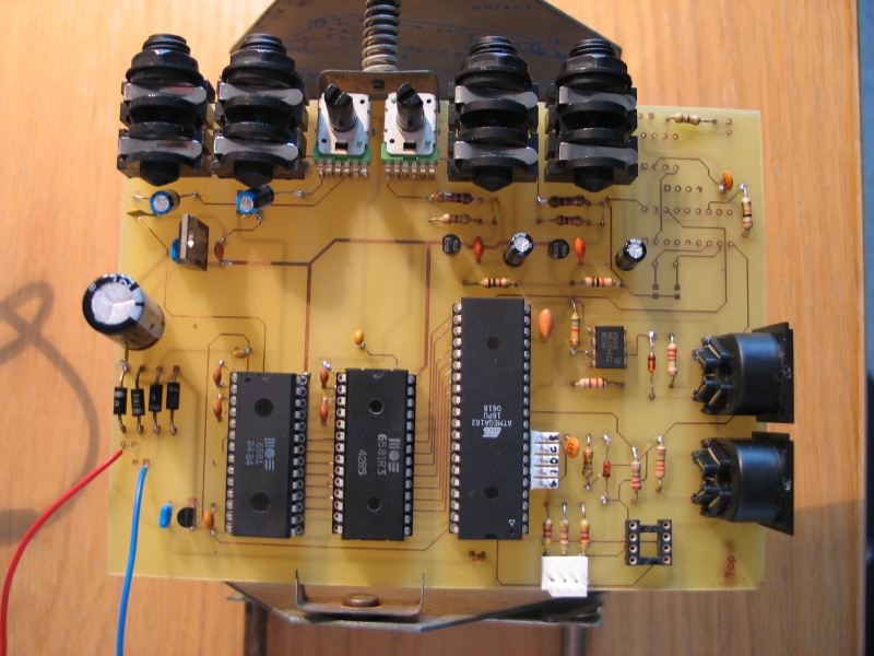
I created my AVR DualSID over the weekend: the hardware is done and working, the software is mostly finished. In the attachment, you can see what it looks like. Nothing fancy, this is really just a test project before I start designing and building a complete synth. The CAN controller and transceiver are currently left out, but they will allow communication with other synths or a control surface in the future. I made a few changes to the first design, mostly simplifying things. The opamps were removed and replaced with a simple emitter follower like in the commodore. Feedback was also left out, since I can easily control it externally. I noticed a significant amplitude difference between the output of the two sids (one R3 and one original it seems). Is this normal? The original also gets a lot hotter. Both are functioning correctly though. Greets, Tom

-
I finished the first design of my dual-sid synth and was hoping to get some comments or ideas on it. This isn't exactly midibox sid stuff since it uses an AVR chip, but I believe it is related enough and I could definitely use the insights of hardcore SID users. I put the design on my webpage: http://research.edm.uhasselt.be/thaber/junk/sid.pdf Some issues that remain: Is 16K memory enough? The feedback control R12 should probably be digitally controllable, but I don't have a digipot that is able to do this yet. I have some but they allow only 0-5V on the inputs, so I would have to change the DC offset to 2.5V. Is 16Mhz enough to drive two SIDs (all control surface things are off-loaded to another device/microcontroller)
-
Hey, I have some MCP6S21's (Programmable Gain Amplifier) chips lying around and was thinking of using them to increase the volume control on the outgoing signal of the SID since the SID has only 4 bit control. The PGA would give an additional 3 bit (+- exponential). I was wondering if this is worth the effort. Some additional circuitry is required to change the DC offset to 2.5V and possible also a divide down to scale the AC swing (the PGA works between 0 and 5V, max AC swing would be 2.5). How much unwanted distortion would the additional circuitry introduce?
-
Oh boy, I've been looking at the circuit and the timings so hard that I missed that obvious fact. Alright, after that quick fix I got a nice little triangle wave coming out of it :) On to the next bit.. Cheers
-
Hey, I got my hands on two SIDs 6581 and I wanted to test them using an AVR chip I had lying around. However, the SID isn't making any sound: I have my oscilloscope hooked up to the OUT pin. All I'm getting is some low noise on a +-7V DC level. The DC level seems to match the datasheet. I used the same setup as the MBHP_SID: two 74hc595's connected to data and address pins, R/W to gnd, the clock is generated by the microcontroller at 880kHz (verified with the scope). I had the clock at 1Mhz before, but I lowered it just in case it was going slightly too fast. I reset the SID before sending my data. It remains high the rest of the time. After setting the address and data, I put CS low for 1ms (far more than required). I also keep it high for 1ms+. I set the following registers: Voice 1 freq = 0x4189 Voice 1 control reg = 0x11 (triangle + gate) Voice 1 attack and decay = 0x00 Voice 1 sustain and release = 0xF0 RES/filt = 0x00 Mode/Vol = 0x0F I've been looking at this for a while now and have no clue what is going wrong. The data and addresses have been verified as well as the clock and chip select pins. Any clues or tips? Kind regards Tom