

warland
-
Posts
16 -
Joined
-
Last visited
Never
Content Type
Profiles
Forums
Blogs
Gallery
Posts posted by warland
-
-
As SLP has said but I will try to answer your questions directly. :)
1. the amount of "expert knowledge" to actually build it is minimal. If you can read a schematic,
understand how to interpret component types and values, can solder and have a general
knowledge of electronic construction practices you should be fine. I would suggest you dig up
some info on basic electronics (plenty is available off the web) and read up first.
2. Read on www.uCApps.de. A couple of guys here sell PCB's and kits you can purchase.
(At a really great price if I may add). You will need to source the SID chips yourself. Again look
around the forums as some guys have a few for sale or hang out at Ebay and look to purchase
a few old Commodore 64's.
3. Time to build will vary on which version you decide to build, experience and how enthusiastic
you are. Take your time as a beginner and don't rush things. Check your work after each step
and DON"T put yourself under any time limits. It is better to work at a steady pace and check
your work than to be chasing problems due to a rushed job.
Look at the WIKI and these SID forums before jumping in and asking too many questions. You
are not the first beginner and it's most likely the questions you wish to ask have been answered
before.
Above all, have fun and enjoy constructing a device that has no peer. There is something really
good about having people say "man, that thing is great" and being able to reply with "I built
it myself" ;D
-
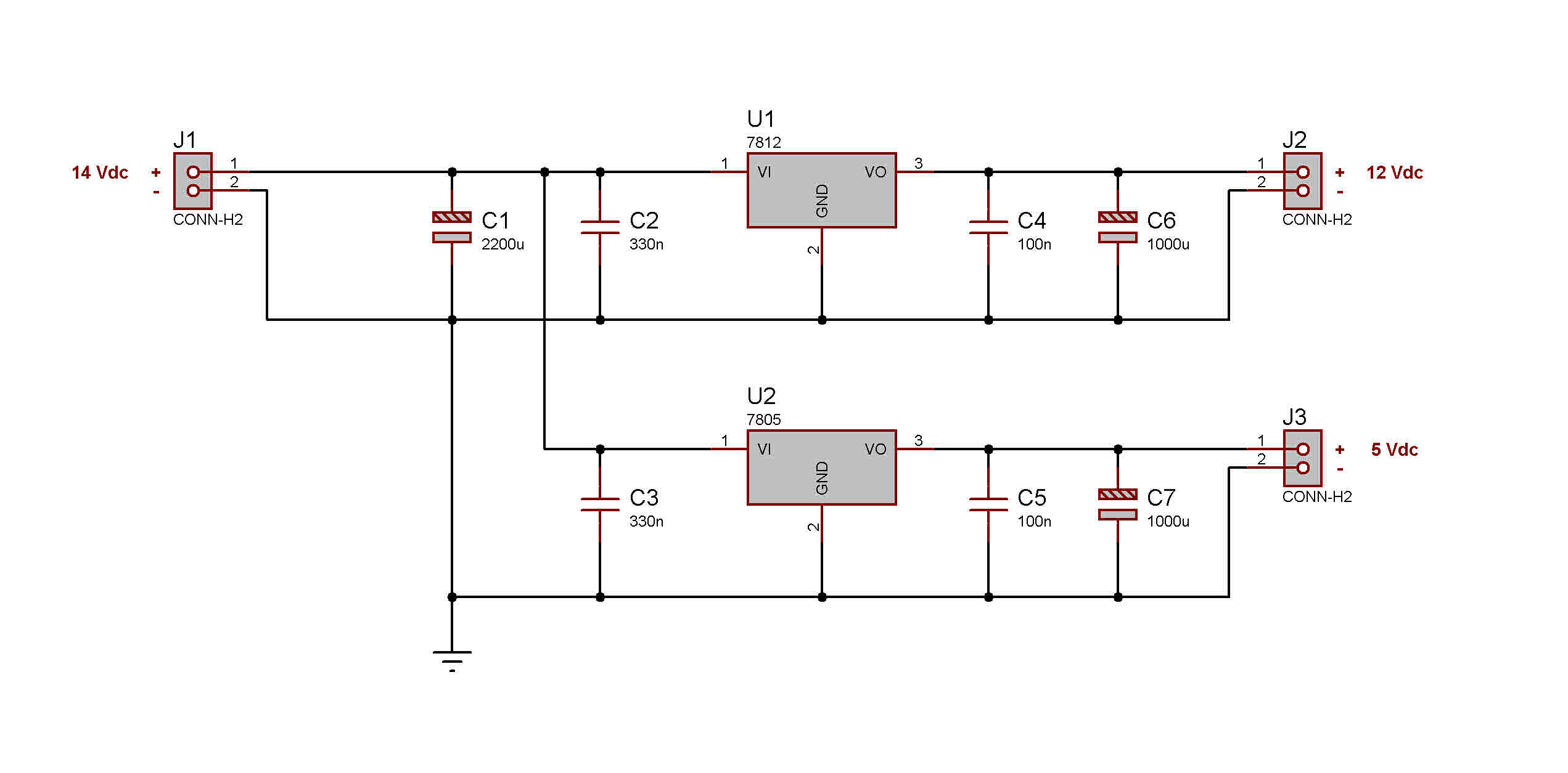
The 13.5 Vdc will most likely shorten the life of the SID considerably. Also SID's
generally run quite warm to hot so the higher voltage will not help. See the attached
schematic as to how I would do it. C1 should have a 25v rating. C6,7 = 16v rating.
Keep the capacitors C2,3,4 and 5 as close as possible to the regulators.
Hope this helps

-
good to hear :)
I haven't seen any that state the rectification method but I guess it's a
case of price will probably dictate the quality ;)
-
To keep costs down, some of the low cost plugpacks simply rectify the 12vac from
the tranny with no filtering at all. I have seen some which dont even use a bridge
recitifier (full wave rectification) and simply use a single diode (half wave rectification)
which produces a large amount of noise (if you look at the DC from a half wave
rectifier you will see that the DC is actually "switching" on and off 50/60 times a
second.
You may need to play around with the value of the filter cap to get rid of all the
noise. Especially if it is only a halfwave recifier. Just make sure that the voltage
rating is no less than 16v, preferably 25v.
It is sometimes worthwhile to pay a bit extra for the fully regulated plugpacks.
-
start by fitting another 2200uf cap between th 12v+ and the common 0v (gnd)
are you sure the plugpack is 12Vdc?
-
glad to be of help.
As a matter of interest, the "ideal" filter capacitor value for placement after
a bridge rectifier can be determined from a simple calculation, C=(I*T)/E
where;
C = capacitor value
I = maximum current draw
T = half cycle time (8.33ms @ 60hz or 10ms @ 50hz)
E = the fall in voltage that will occur during one half cycle
The capacitor selected must have a voltage rating of at least 20% more than the expected
DC voltage output of the bridge rectifier. It is fine to go way over value (eg using a 100v
rated cap on a 12 supply) but never less, unless of course you dont mind your filter
cap going bang or shorting out!! The 20% allows for any fluctuation or spiking that may
occur. Most countries supply AC with a reasonably tight tolerance to the rated value but
in some circumstances this can vary considerably.
-
Toroidal transformers are always the best choice over other transformer designs.
In simple terms they are more efficient and due to the "closed" magnetic aspects
of their construction are less prone to produce EMF type noise.
As to fusing, remember a fuse or circuit breaker is intended to protect what comes
after it in the circuit, NOT what comes before it. In this schematic a fuse of no more
than the primary winding's rated current should be fitted. In this case I would fit a
500mA fast blow in the "live" wire of the primary. This particular tranny appears to
have a tapped primary for connection to 2 different supply voltages. (probably 110
or 220-240). Never fit a fuse in the return or neutral side of the primary as if this
blows and the device is still connected to the AC supply, a lethal voltage is still present
on the tranny.
The secondaries should be protected by a 1 Amp slow blow on each secondary. In this
case one in connected between the white wire and the bridge rectifier and one connected
between the green wire and it's bridge rectifier should be sufficient.
-
My suggestion is to build the SID modules including ALL PSU components as shown in the original SID schematic.
Build the optimised PSU as per the schematic without any modification at all.
On each core module leave out IC3 (7805 voltage regulator)and fit a bridge wire between pins 1 and 3 of this regulators PCB pads (the 2 outer ones), leave out X1, leave out C6 (330nF), leave out C4 (10uF) and in place of C5 (2200uF) fit a 1000uF/16v electrolytic capacitor.
A standard 78xxT series regulator is good for an output of 1 Amp. If fitted with a good heat sink this can rise to around 1.4 - 1.5 amps. If possible I would fit one of the 2 A rated 7805's if using in a system with multiple cores and sid's
Hope this is clear and helps.
-
???
I think my view on what has been happening on ebay is quite obvious.
As to your second statement I don't see what you are getting at !
I have been kicking around (though I admit not a lot of posting) since
2003. Previously with the nick cem3340. I have had contact with TK
at times since his first midibox (16F84 based) way long ago. I have
quietly been developing various MIOS devices over that period all of
which now work happily in my studio. I am currently developing an
8 channel Drum synth (fully programmable, with program storage)
and a true analog synth voice card which will again be fully programmable,
have program storage etc. This when mated with MIOS will be expandable
so as to allow 6 note poly. (Using a similar method as the SID synth..ie.
1 core per voice)
I have been tempted many times to post up all the details, code, schematics
etc over the years. At this point I simply wont do it for the fact of people
like bluelantern and those who condone his/her activities.
So no more from me on this ebay stuff. Sorry to hijack the thread with my
waffle.
-
Simple, lock this thread :-X I understand your point of view and maybe it is floggin
a dead horse, but sometimes the horse is just sleeping. It's not my IP being sold
so I suppose it's cool. It's not for me to decide if the work of the community is of
no value and like most "democracies" freedom of speech is not truly free.
Every now and then god dies and someone is elected to walk in his footsteps, so
now is the time to probably lay down and admit defeat.
???
-
I don't like kicking someone for there idea of taste and design concept but this guy
is just unbelievable. Ok, what he does is wrong with regards to using unnameised
IP, but it goes beyond that. He is making big bucks from other peoples lack of knowledge.
Really, I find it distasteful that he passes of his 3rd world quality workmanship
as something of value. My 12yr old daughter builds better gear than this stuff!!
No amount of "coloured acrylic" bling or hotmelt glue can disguise the fact that
this chap bangs these boxes together in a few hours with his only regard being
to make as much money from the nieve as possible >:(
From his recent sales ;
11 units sold, highest price $510.00us, lowest price $115.06us, average price $314.00us
net income $3457.06
Sales history...Aug 1...Sept 4....Oct 6.
Now if you assume he will sell 11 every 3 mths, using his current figures he will
make an income of around $13828us a year from this scam. :o with not one cent
going to the person (people) who made his little business possible.
And why the sudden USA sales only policy...has he been the "victim" of a purchase
scam himself?......I hope so ;D
-
There are 2 reasons I can think of ;
1) It may be that only the full versions (ie not demo or function limited) of the mentioned software
will allow full checking of the Houston emulation
2) Not wanting to be associated with any dodgy (ie cracked) versions of the steinberg apps :o
-
I'm an electronics tech by trade and see problems like this at times.
Double check that ALL solder joints are good, hidden dry or bad joints
can cause issues.
Check for any shorts between PCB tracks. I have seen tiny "whiskers"
of solder that once a PCB is warm caused shorting before. You need
to use a magnifying glass to check.
Have you tried using another 18F4685?
Is there "noise" on the powersupply output?
If all the "hardware" side of things look ok, have you tried re-downloading
the SID file from the website and re-loaded that version. You may have
a corrupted application file.
All that said, does the reboot occur if no SID chips are fitted to the PCB but
with the PIC running the SID app?
-
Even under GPL licensing it is probable the guy is in breach of the licensing terms.
His ad on ebay should clearly state that the device is covered by the GPL conditions
and his device being sold should also be supplied with a copy of such license and
all required documentation.
See: http://www.gnu.org/licenses/gpl-violation.html
I'm no legal eagle but a good read through the GPL conditions have surfaced a number
of areas it could be argued a breach has occured.
-
I have a bit of a question regarding reading a key matrix. To add fuel to the current fire
I'm wondering if it's possible to scan a matrix but sensing a variable voltage at each
crosspoint. In older keyboards, velocity was sensed by timing the crossover from a normally
closed contact to a normally open contact on each key. Thus the quicker the change over
the higher the velocity.
Recent keyboards use a dynamic rubber button arrangement. On closure, the voltage output
depends on the resistance at the time of closure. It works on the principle the harder the
key is pressed the lower the contact resistance and therefore the higher the voltage at the time
of reading. As an aside to this principle, it also allows aftertouch to be applied as well.
On each scan, new key voltages are read and a midi note and velocity value sent. If a key scanned
is already "flagged" as being on, the current voltage is read and sent as an aftertouch value.
I hope my rough description is enough for someone to answer whether it is viable to use this approach with MIOS. I have a number of keyboard assemblies that use dynamic rubber contacts
I could use if this could be achieved. :)

Inside - Poly Evolver, Nord Lead 3, Virus TI, pulse, XT & Andromeda (updated)
in Miscellaneous
Posted
Just trawling thru some older posts and noticed the mention of the evolver.
As many of you will know OnChip is the current name of the company once
known as CEM.
The chips used in the Evolver for analog signal processing are the PA397's.
These are a tweaked version of the CEM3396 as used in the Obi matrix
6 and 1000. Also used in the Cheetah MS6. If you ask nicely and order
about 25,000 of them, OnChip will make you some..=)