

abcmann
-
Posts
70 -
Joined
-
Last visited
Never
Content Type
Profiles
Forums
Blogs
Gallery
Posts posted by abcmann
-
-
Löte mal die Pull Up Widerstände nochma neu. Wenn das nicht hilft tausch mal das IC aus.
Grüsse
-
Wooo :D
Das ist die Anti-Falten Cam ^^
Schöne LC unter Andrem. *thumpsUP*
Würd gern auch schon meine anfangen, aber leider fehlt imMo das nötige Kleingeld.
Viel Spass weiterhin.
-
Aus reinem Interesse:
Wieso entfernst du das copyright von den Platinen ? (siehe Bild P1020737)
Grüsse
-
all sold
except the max525's
-
Hi
I need some money so I have to sell some of my project now. It's really damn difficult for me, but really bneed the money for paying some bills.
to sell:
- 1x spare MB6582 Main PCB from the 1st bulk order (the red one).
17,50€ + shipping
- 1x sashas x0xb0x pcb ( Powerpcb with powerparts nearly ready soldered + main pcb unsoldered)
with rare parts 2x 6562; 3x C1583 97G; 1x K30A-Y; 1x K30A-O; 1x C2291 82G; 1x BA6110, all new ones!
50 € + shipping
- 1x GM5 soldered on original GM5 PCB, some other parts already soldered
8 € + shipping
- 2x MAX525 ACPP (new) (+ shunt if you take both)
25 € each + shipping
- 2x seppos SSM2044 filter pcb with resistors already soldered
5 € each + shipping (with SSM's 15 euro each)
120 € for everything excl. shipping costs.
please pm me.
bye
-
You dont need to use those 5-pin DIN connectors if you mean that. The cable itself is a normal 3-pole, shielded cable. You can take a cheap stereo microphone cable and solder it directly to the pins.
I THINK the ground is just to shield the inside of the cable against radiatons from outside. (Please correct me someone if I am wrong here). So, if you wire it internally and the connection is not very long, you can use 2 pieces of a normal ribbon cable and let the ground away for that few centimeters.
For GM5: Did you add a optocoupler etc. for the other IOs ?
For moderator: Change this to the english section because it gets too long ?
greets
-
the problem of amigafalcon was, that he used 2 seperate psu's for the core and the gm5. That NEEDs an optocoupler between them. If you power the gm5 and the core from the same psu (usb or ONE psu for both / not usbpower-psupower mixed or 2 psus! ) you can leave the optocoupler out.
But I'll point to the 2 hours amigafalcon spent, because he left out the opto and get an error because nobody thought of that (even simple?!) problem before.
Can't you find a PC900 optocoupler in your area? You'd have to exchange some pins or built a very small pcb for adapting the pinout.
USB poweres up to 500mA. You have to calculate or measure with a multimeter how much current your box will need. But I think that should work ( if you dont use a backlit lcd at all)
-
Yepp, thats what I meant. :D
The envelope follower can also act as a "sidechain", when you use the measured volume to set a parameter of another channel.
For example volume of input d changes filter of channel a ...................
-
Hi, I'd like to start my first own project. I just have some basic ideas of it, so I decided to post it in design concepts firstly. I've ordered the last missing parts already. The casing isnt built yet, because I first need to know how my box should work when its ready.
Like you perhaps already read, it should get into a filter fx.
What should this baby do ?
- 4 independent ins and outs
Four channels, ..... so 1 aout module, 2 ssm pcbs and 4 ssm's.
- Envelope Detector circuit
there are some circuits on the net. It's output should be read with an AIN
and should be assigable to every parameter
- 3 envelopes with DADSR per channel
freely assignable to the env.detector / frequency / resonance
triggered by env.detector value or by midi
- some lfo's
freely assignable to all parameters of the envelopes and filters
based on realtime or midiclock/BPM
- routing the filter in series or parallel
I think to use MAX4550. I have several here.
Its a dual 4in/2out crosspoint switch.
- feedback loop
some shapes if ideas, but nothing more yet
any suggestions from you ?
bye
-
what can you do with just 2 simple logic ic's ????
nothing big, but not "standard" and so just cool ^^
-
sold , thank you
-
I am selling 2 SID 8580R5.
Price is 15 Euro each + shipping
Location: Germany
greets
-
1. crossposting is hier nich gern gesehen
2. Junge, ........, nochma, ........ ohne LESEN wird dir keiner helfen (können) !!!!
Was kann die MB64E ????
|| Implemented:
||
0%| o 128 virtual pots which can be controlled with up to <==============
|| 64 rotary encoders
|| o Rotary Encoder Handler with interpolator (quadroubled resolution)
|| Example: a STEC16B normaly sends 24 pulses per revolution, but
|| the MIOS driver reacts on every falling and rising edge, this
|| results to 96 steps per revolution!
|| o up to 64 buttons, 64 LEDs (like MIDIbox64) <==============
|| o independent selection of parameters (1 of 128) on-the-fly
|| o BankStick support (+4*8=32 banks with every BankStick)
|| o support for 2*16 display
|| o support for (optional) LED-Rings with up to 16*16 LEDs
|| o 4 customizable LED-Ring patterns in every bank
|| o Menu with 2 cursor and 1 exec button
|| o Different Display Modes
|| o Named Events (requires BankStick)
|| o Snapshot Button with Save/Recall behaviour
|| o MIDI Learn Mode for every encoder
|| o MIDI Learn for Single encoder, automatic row channel,
|| automatic row add
|| o Meta Events allow you to define SysEx strings and more
|| o MIDI Merger
|| o Exchange setups via SysEx
|| o min/max values for encoders
|| o Sending absolute values: xx xx [from min to max]
|| o Sending relative events: xx xx 40 +/- speed
|| o Sending relative events: xx xx 00 +/- speed
|| o Sending relative events: xx xx 40 +/- 1
|| o Sending relative events: xx xx 00 +/- 1
|| o Sending relative CC events: CC Inc/Dec xx
|| o Progressive Mode for Encoders (faster turns: higher inc/dec)
|| o "Fast" Button to enable the progressive mode
|| o "Slow" Button
|| o different button behaviour like on MIDIbox Plus
|| o optional MIDI event filter for the merger
||
|| Additional features provided by the MIOS based version:
|| o runs on a PIC18F452 under MIOS
|| o On-Screen editing of MIDI Events
|| o On-Screen editing of pot lables
|| o On-Screen editing of banknames
|| o up to 8 BankSticks can be connected (-> up to 64 banks)
|| o Remote Control via SysEx
|| o banks can be copied
|| o an optional global MIDI channel
|| o Morphing function which allows to fade smoothly between two pot scenes
|| o optionally up to 64 pots or up to 8 motorfaders can be connected <==============
|| in addition to the rotary encoders
||
100%|
||
\/
MB64 hat auch nur 64 dig. Eingänge INKLUSIVE Encoder. Das heisst auch wenn du die Software ändersqt musst du pro Core immer noch mit 64 Eingängen an deinen DINs arbeiten.
-
@cimo:
Perhaps you already know, but I was thinking about this too, and i want to replace ALL the encoders by pots. So I need more than 5 inputs.
2 x midi mergers and 2 x 74HC00 (like LTC-module) are needed if you want to record the parameterchanges made by the 64. Even when you can control your SID with a MB64 before it, the SID wont forward the cc or nrpn before the internal Midi-Merger of your SID is enabled. For softwareupdates or for controlling your SID from another piece of hardware (like your pc) you'll need to activate the internal Midi-Merger of the MB64, TOO.
But that causes again another problem, ...... , every data what is coming from your midioutput => to your sid and 64 will run THROUGH both to the input of your pc (or whatever) again. I think that really isn't what you are looking for.
A "should be" working solution can be found in this post:
http://www.midibox.org/forum/index.php/topic,12105.msg99514.html#msg99514
The yellow boxes indicate the 2 needed midi-mergers (2 cores)
As you can see, the outcoming MIDI-Data from the "host" and the mb64 needs to feed 2 inputs each. You can't solder the output directly to both inputs without an additional IC between. Look at the LTC-Module. With the 74HC00 you can make 2 signals from 1.
So you need:
- 2 additional cores for midi-mergers
- 2 74HC00 circuits for doubling the outputs
abc
ADDED:
All this won't replace the layer functions !!! These must be implemented into the MB64 if you want this.
I havent tried this method or julienvoirin's what he used in that post. But both could help you. I think that this MBLink Start and Endpoint thing could do that job too.
-
Nich verzweifeln ....... lesen!!!!
Hättest du dir schon mal MB64E mal genauer angeschaut hättest du bemerkt dass in dieser Software bereits Encoder+Pots+Buttons nativ unterstützt werden.
Habs noch nich gemacht aber das Prozedere wird etwa so aussehen:
- MB64E Quellcode runterladen und anschauen
- Überblick gewinnen welche Datei für was ist und welche interessant sein könnte
- suchen wo was über "pots" steht
- dort angeben wie viele pots / multiplexer (4051) es gibt
- den leicht modifizierten Quelltext zur hex kompilieren und ab aufn pic
wie immer ohne Gewähr für Richtigkeit, ist nur "in etwa" und kann/wird in der genauen Vorgehensweise abweichen ..... generell gilt es nur im Quelltext "pots" zu aktivieren, und zu sagen wie viele. "Verarbeiten können" tut das die Software schon.
aber dass wirst du schon hinbekommen mit etwas Hilfe und eigenem Köpfchen.....
Viel Spaß ;P
-
these pics should show you how it works

this could be the contact plate
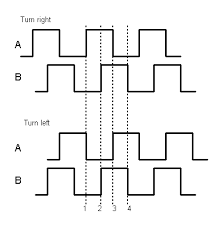
this is the output when turning the encoder
-
In einem Encoder sind einfach 2 Schalter. Die Kontakte schliessen beim drehen jeweils nacheinander. Schaltet Kontakt A vor B dreht man halt in die eine Richtung. Schliesst dann aber auf einmal B vor A dreht man logischerweise andersrum.
Mit jedem "Klick" erhöht oder senkt man einen Wert.
Deine Applikation auf dem Core geht wohl davon aus dass du SCHALTER und keinen Encoder angschlossen hast. Ich sag mal " Die Applikation "zählt" gerade nicht mit. "
Genau dies muss sie aber auf diesen Pins deines DIN machen. (da du ja nen Encoder da hast an 2 Anschlüssen).
Midibox64 hat in seiner Applikation als Standard soweit ich weiss NUR Pots und Taster vorgesehen. Mit Midibox64E kannst du in der Standardkonfiguration Encoder anschliessen.
Wenn du nun Pots und Encoder gemischt betreiben möchtest musst du eben entweder 2 cores mit standardapplikation benutzen, odeeeer mit etwas codingschnippelei alles in einer software unterbringen.
Kann dir jetzt nicht alles erklären, aber die Eckdaten damit du mit deinem Problem weiterkommst solltest du jetzt haben.
Grüsse
:P :P :P
-
hmmmm, perhaps you can give something with it. I dont suppose much people will exchange a expensive dac for a cheap 90 cent shunt
perhaps you have luck.
peace
-
I tried this this mixer too. Its REALLY not feeling like Behringer...... and thats meant a good way ;P
The only thing what could be better are the sliders.
If it doesnt disambles itself and if the pots wont suck after 2 month this is really a very reasonable mixer !
-
ill do that. i dont know if it helps, but there is the c sourcecode in the package. perhaps anybody can use it to run it under linux.
-
will this only be developed on the new stm32 module or on the old core too now ??
-
Hi, I found this today.....
it looks really good for the most purposes. Better than a soundcard scope.
http://jonw0224.tripod.com/ppmscope.html
Specifications and Goal Feature List:
--------------------------------------------------
Feature
Current Version (v.2.01)
Goal Version
Sample Rate
Variable, single shot 1 MHz max, interlaced 151 kHz max
Variable, single shot max 1 MHz, interlaced max 417 kHz, repetitive 5 MHz
Bandwidth
500 kHz
500 kHz
Number of Channels
Two
Two
Sample Depth
256 bytes per channel, 128 bytes per channel when interlaced
256 bytes per channel, 128 bytes per channel when interlaced
Sample Modes
Single shot and interlaced
Single shot, interlaced channel, and repetitive
Calibration
Voltage offset
Voltage per division and voltage offset calibration
Configuration Settings
Configuration of default and saving of settings for future use
Configuration of default and saving of settings for future use
Hardware Connection
Any parallel port
Any parallel, serial, or USB port
Coupling
AC and DC, reflected on PC
AC and DC, reflected on PC
Channel gain
Gain of 1, 2, and 5, reflected on PC
Gain of 1, 2, and 5, reflected on PC
Trigger
Variable level, slope, and timing
Variable level, slope, and timing
Frequency Spectrum
Yes
Yes
Waveform Reconstruction
Triangle, square, point, and sinc
Triangle, square, point, and sinc
XY view
Yes
Yes
Channel offset and volt per division settings
Yes
Yes
Cursors
Yes
Yes
Math functions
Only addition and subtraction of channels
Addition, subtraction, auto period, auto peak-to-peak, etc.
Waveform export
Comma delimited
Bitmap and comma delimited
I'll build one :D
bye
-
And this one ?
http://www.thomann.de/de/thon_rackblende_1he_8xlr.htm
It's with 8 holes. If you mount the original pcb with 2 midi sockes and the usb jack, it'll fit very good i think.
-
Das sind die Kondensatoren des Filters. Kann man tauschen, ergibts dann aber veränderte filtersweeps. Einfach mal testen ;P
Hilfe bei Din Modul
in Deutsch
Posted
In der Mitte sind die 2 rails für Spannung und masse.
Den Kondensator mit einer Seite möglichst nahe dort hin wo das stromversorgende Beinchen des darüberliegenden IC rauskommt, und das andere irgendwo auf Masse.
Grüsse