

Filch
-
Posts
78 -
Joined
-
Last visited
Content Type
Profiles
Forums
Blogs
Gallery
Posts posted by Filch
-
-
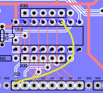
Thanks for the response. Just so I don't make any poor assumptions, here's a pic of what I think you are suggesting for JD1.
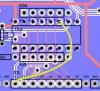
Did I screwup the pin count here? Here's where a slight confusion for me happens when it comes to the Pin number. I was under the impression pin 1 on an IC was the left side pin with the dot/notch, continued down the side, then started on the right side and on down. I was thinking the pin I've connected to in the pic for U16 was pin 14??
Or I'm just completely wrong about pin order or where I think this wire should be connecting and it is actually pin 11, 3 up from the one in my picture.
-
I ended up lifting 2 pads off of a Rev2 MB-6582 baseboard when desoldering some items. I was hoping someone may help me identify if and where I'll need to attach some flying wires to fix the flub I made.
On the topside of the board, I lifted pad for R43 near U22.
- if I'm reading the board layout properly, I should just be able to bridge solder on the bottom of the board from R43 to the socket pin?
On the bottom of the board, I lifted pad D0 for JD1
- this one looks a little more complex and not exactly sure what the best action for repair is. Could I run a flying wire from D0 to the small hole joining the last two pins of resistor network?
Convenient link to the baseboard PCB layout :
-
So it could have been bad contacton the P1 wiper, or current draw close to current supply limit. If you're happy with the brightness where it is, then it ain't broke, don't fix it, nothing to see here move along.... ;)
I'm guessing the later, If I turned P1 most of the way up, the box would reboot.
-
I turned P1 all the way down and I haven't noticed any more of the flickering. The screen is still plenty bright at this setting. I'll keep playing around with the sammichSID and see if it flickers again, but for now it appears to have disappeared.
Thanks
-
I've just completed and tested my sammichSID kit and for the first time ever, I completed a kit with no mistakes, no bugs, and no errors. I want to thank Wilba for a most excellent piece of kit and fantastic instructional writing. I think it's a testament to how well this was designed and want to thank you again.
And now for one one, minor issue..... ;)
MY LCD gets occasional flicker and dimming. It's slight, but noticeable. Is this normal or is there something I should start looking at as the cause?
Thanks!
-
did i mention that this works only for the lead engine? :-P
I will be trying this soon. I love M4L and I have several HW synths that I want to build editors for. I plan to use yours here as a guide in helping me. I haven't built a thing in max yet.
I want to be able to do full sysex as well since many of my other synths will do sysex only. If you know of a workaround to work sysex control into Live, please let me pick your brain.
-
All the switchmode power supplies I've tried put noise on the audio outputs. They are not recommended (as I've stated in the build guide).
Ha. I guess I probably should have realized switching/switchmode were one in the same. Should've figured there would be something wrong with this. :-p
Hopefully I can redeem myself with this :
It's the last model on this pdf :
Linear PSU Model : ST-1212-R0.5A
And here it is on Amazon for $11.95 US after shipping
-
I found this pretty cheap wallwart on Amazon.com and looks like to be a good candidate and another source for a PSU. I intend to use this with my 6582 sammich.
* Fully Regulated 100V-240V can be used world wide
* 12V DC 500MA Switching Power Supply
* 6 Ft Long cord with center positive 2.1 MM jack
-
If you haven't already, double check that your LCD board isn't shorting on the CS. This has been the cause of many weird and wild problems in the past.
-
Cool, will do. I've a horrible feeling it's not going to work, but fingers crossed I might be wrong...
a|x
It will work, but only using CC's. Ableton Live filters all sysex, even though Max has no trouble with Sysex, it's hosted in Live, therefore it will never makes it into Live, recorded or otherwise. There is some mild rumors about sysex support in the future, but Ableton is purely focused on bug squashing right now and will not be adding new features anytime soon.
-
FWIW I didn't use any insulation, tape, etc. I just used a small nut on each screw between the PCB and the LCD to offset the LCD below the board far enough so it won't short: http://picasaweb.google.com/fussylizard/MB6582?authkey=Gv1sRgCM7npqbPgvbfYA&feat=directlink#5359892899542622770
Glad you got it working though!
I actually noticed your post for that when I searched for LCD Insulation. I think I'll do that as well as taping up the PCB (which I've already done). My screws are a little small though, so I may stack 2 washers instead for a gap.
My problem now is that with all this futzing around troubleshooting the issue, I've broke a few wire leads on some of the ribbon cables between the CS and the mainboard.... *sigh*
-
I was using the LCD to determine if I was getting the error still or not. The CS was not responding normally. Most of it was, other parts were acting strange. When I did your test, I was getting the same errors on the LCD.
So, I detached the LCD from the CS and the problems went away! :D Looks like I've got a short somewhere. I already had the pads covered in electrical tape. I'll just wrap the rest of the exposed LCD PCB in electrical tape. Thanks Wilba!!!
I'm going to have to remove the front panel to get the LCD attached again. I was trying to avoid taking these apart as I fear I'm going to squish some LEDs when putting the front panel back on. My panel fitting is a bit snug. I have to nudge a button here and there to get it to slide on properly.
-
Spoke briefly to Wilba about this problem in the chat room. I was suspect of my CS causing the problem since the mainboard was working okay before I wired up the CS. He suggested removing the Shift Registers and see if the problem goes away.
I removed them all and my error did disappear. I replaced them one by one to see where the problem began. I started with the 165's and all was well until I placed in the 5th 165 into U20. I thought I may have a short or bald solder point there. I reflowed all the points and came back with the same problem. To make sure the shift register wasn't bad, I removed it and put the one from U19 into U20 and I had no errors. I thought I may have found a bad IC, but to be thorough, I put that suspect IC into U19, removed the IC I had in U20, and no errors again.
The only time I get this error is when all 5 165 shift registers are in place. The problem goes away when I remove any one of the 165's, it doesn't matter which one. Removing one or all of the 595's does not change anything.
-
I reupped the SID OS to all 4 cores again, and now I'm back to SID4 Not Available (No MBNet Response)
-
I've finally finished getting my CS surface wired up to the main board. When I turned it on the first time, I got an error stating 'SID4 not available' and '(No MBNet Response)'. I found another thread with the same issue and after reflashing the MIOS, the problem cleared.
I've reflashed the MIOS to 1.9g on all cores. I get READY on all 4 cores. I then loaded the latest MB-6582 SID OS and now I'm getting the following error.
SID4 not available (Can Bus Errors).
R80 is in place, all the jumpers are in place. I wasn't getting any errors until I connected the control surface. Any suggestions of where I should begin looking to resolve this issue?
-
The 250010902 cable has eight wires and may work better for that reason. If you don't want to buy 60 of these you might want to see if they'll send you some free samples. I'm trying to see if they'll send me a few for my MB.
I already ordered them and I'm already in possession of them :)
-
I also wanted to mention that you can do your own "piping" of the JB Weld by putting it into a ziplock bag into the corner. You then just cut off the corner and you can squeeze out the JB Weld with little mess.
I just got my panel from FPE. I'm just waiting on the standoffs from Mouser and I'll finally bring my MB-6582 build to a close. :)
-
LOL,
I literally purchased panels from FPE minutes before you posted this. Oh well :)
-
I used standard IDC cable since that's what I had, and I couldn't find the other stuff on Mouser (I'm sure it's there, but I just couldn't find it). The standard IDC cable seems fine to me.
I found some, but you can only get it in a 100' roll for $54
Mouser Part #82-28-6081
I'm still trying to locate a cheaper source or smaller quantity
**EDIT**
I just found this. .100 , 6 inches long, 9 wire. This is near perfect. I have to buy a minimum of 60 of these though. So I will have a ton of extra ones to get rid of. I'll see how they are when I get them
-
And also I bit my tongue not to say: "Best way for placing CS risers AFTER a board has been populated: Time machine" ;) Man one of those things would be handy. Just a 20 second go-back-only one would do. Kinda like real-life edit -> undo :D
I wish I wish I wish..... *taps heels 3 times*
-
I am assuming you mean the MB-6582 CS PCB...
Yep, my bad. Forgive me.
Thanks so much for the advice on that.
-
Ahhh... no worries... I just didn't want to have missed it or had it filtered into SPAM and be the a-hole who didn't put up his money.
-
I populated my CS pcb (not the LED's yet) b/c I had anticipated participating in the front panel group buy that was going on. Now that it looks unlikely for that to happen any time in the near future, what's the best advice for me to attempt to get the risers correctly attached now that I have most of the board filled in with components?
The guide says to do this BEFORE soldering in components, so I'm worried.
-
I never got an invoice, or are you still going through the list?
MB-6582 baseboard : lifted pad work arounds
in MIDIbox SID
Posted
Wow, all this time and didn't realize it went counterclockwise.
Thanks for everyone's help :)