Simson91
-
Posts
24 -
Joined
-
Last visited
Never
Simson91's Achievements
MIDIbox Newbie (1/4)
0
Reputation
-
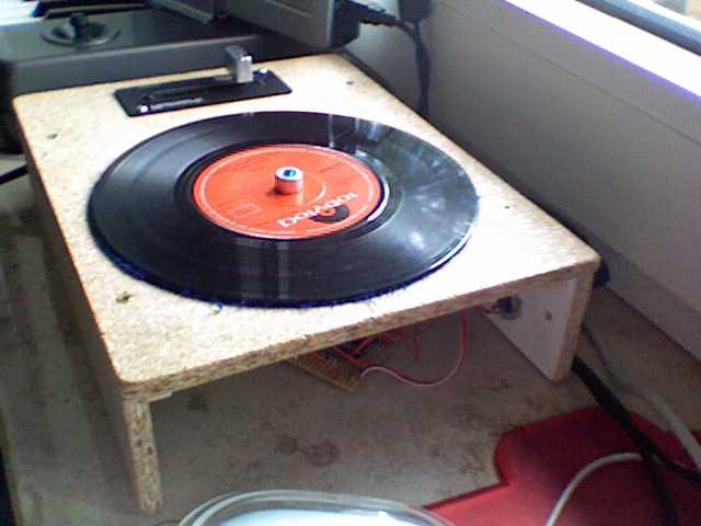
Some pictures of the box and a little sideview. Sorry for the bad quality of the pictures (my digicam is simply crap) and the poor drawing :) I'm still looking for conductive paint, couldn't find any, does anyone know in which kind of store I should look for it, in germany? Some things I'd like to add is a little power LED which woun't be a problem but I'll try to design it like the speed calibration strobe of an real turntable and maybe one or two real cool looking buttons but thats future stuff. Simon HPIM6398.JPG HPIM6400.JPG
-
[solved] Encoder problem and other "scratch box" issues
Simson91 replied to Simson91's topic in Testing/Troubleshooting
All right, I'll post the rest of my stuff in the scratch wheel thread, since its not really about this topic anymore. :) Thanks again rasteri, I hope this will be a very helpful thread for anyone who wants to build that box. Simon -
[solved] Encoder problem and other "scratch box" issues
Simson91 replied to Simson91's topic in Testing/Troubleshooting
I'll probaly send this fader back. I could open it but I would loose my warranty. I'm not sure if I should try a different one or get the same one again to see if the problem was this fader. Oh and I took the measurements directly on the pins of the fader. !EDIT: All right, I opened the fader and I was lucky, one of the little wipers was like a millimeter from the contact, so I bend it down aand... It works perfectly. I connected everything and my crossfader is now up and running in traktor. Thanks for all your help rasteri! I'll try to get some conductive paint to get my vinyl to work as the touch sensor and my box is gonna be completed. EDIT: Picture of "beta wooden box" :) Thanks again Simon -
[solved] Encoder problem and other "scratch box" issues
Simson91 replied to Simson91's topic in Testing/Troubleshooting
Some weird stuff: The voltage on the two fixed points is 5V like it should be I guess but on the wiper the voltage is 0,3V and it doesn't change when I move the fader. ??? ??? resistance between 1+2 = not connected (too big to measure) resistance between 1+3 = not connected?? resistance between 2+3 = 50k the problem is I don't see any changes when I move the fader, that is very strange to me. EDIT measured the resistance between 1+3 again (my multimeter seemed to go crazy) and got no connection either. And the one between 2+3 is 50k ...man this thing got me nuts ::) -
[solved] Encoder problem and other "scratch box" issues
Simson91 replied to Simson91's topic in Testing/Troubleshooting
I just connected everything like you said above, if I don't ground pin2 it goes loco when I touch the case of the fader or do something else like spin the wheel. If I ground pin2 like it was before (because otherwise it would go crazy) I don't get any signal (then there is no voltage on the wiper either. Maybe it needs to be grounded through a resistor like the photodiodes? :) -
[solved] Encoder problem and other "scratch box" issues
Simson91 replied to Simson91's topic in Testing/Troubleshooting
Does someone know how to connect these 3 pins to my module? ::) I thought it be easy but after thinking about it a while I'm not too sure anymore. -
[solved] Encoder problem and other "scratch box" issues
Simson91 replied to Simson91's topic in Testing/Troubleshooting
Yeah thats what I'll probaly do. According to this picture I thought I'd be pretty easy to use. -
[solved] Encoder problem and other "scratch box" issues
Simson91 replied to Simson91's topic in Testing/Troubleshooting
Just for test purposes I ordered the Numark CP-Pro as used in the whole Numark DXM series. It's probaly not a very good fader but someone told me its underrated. It will work for me since I'm not really a scratch pro. I'll get it tonight :) /edit: Of course I will get a better one if everything works fine and if it would improve my sound :) -
[solved] Encoder problem and other "scratch box" issues
Simson91 replied to Simson91's topic in Testing/Troubleshooting
;D ;D ;D WORKS perfectly, all right today my crossfader should be here and then I'll post a video if anyone is interested. -
[solved] Encoder problem and other "scratch box" issues
Simson91 replied to Simson91's topic in Testing/Troubleshooting
Hey rasteri, I really have to apologize for that, sorry. So I uncomment the use adc encoder lines but then I didn't save it and tried to compile it. Anyways, it works, I compiled the code umploaded it and the touch sensor officially works, thanks! There is one thing though, the encoder doesn't work anymore. Maybe I forgot to change something in the voltage for encoder comparators? I guess it can't be too hard to fix since it worked with the first release of your code. I was really happy to see the touch sensor work though, thanks so much for going over everything with me again. Simon -
[solved] Encoder problem and other "scratch box" issues
Simson91 replied to Simson91's topic in Testing/Troubleshooting
Thats was indeed my fault. Somehow I got a prblem compiling the code: Linking Project error: missing definition for symbol "_CVRCONbits", required by "_output\main.o" error: missing definition for symbol "_CVRCON", required by "_output\main.o" error: missing definition for symbol "_CMCONbits", required by "_output\main.o" I didn't expect that. Maybe its more simple if you or someone else could send me the .hex file? Thanks Simon -
[solved] Encoder problem and other "scratch box" issues
Simson91 replied to Simson91's topic in Testing/Troubleshooting
Now I don't have any voltage in there. RD1 shows barley 0.03 and RD4 0V ... Do I have to put the 5V anywhere in the circuit or should it come from one of the pins? Another question: I'm still using the first code that you uploaded, does it even include the touch sensor? because I noticed that you posted it before you came out with the touch sensor capability. -
[solved] Encoder problem and other "scratch box" issues
Simson91 replied to Simson91's topic in Testing/Troubleshooting
:D Thanks,all my respect goes to you because you did it without an instruction and I'm just using the stuff you put online, so asking some questions or stumbling over some little errors are things I'll have to go through other wise it would be boring. ::) You were right, I had a 10k pullup resistor on RD1, so I'm gonna remove that whole part now (so no 5V at RD1 either right?) and will be back with some (hopefully) good news soon. :) Simon -
[solved] Encoder problem and other "scratch box" issues
Simson91 replied to Simson91's topic in Testing/Troubleshooting
Hey, I just built in the 360K resistor but I still don't get any output .. there is still no ( well 0.01V) voltage on RD4 or J14... I'll to express how I connected everything: RD1 (4.9V) ----360K-----RD4 l l wire to touch I hope you guys kind of see how it is, its weird because there realy is not much that could possibly go wrong. Thanks Simon -
[solved] Encoder problem and other "scratch box" issues
Simson91 replied to Simson91's topic in Testing/Troubleshooting
All right, I don't have a 360K resistor laying around, so I'll get one tomorrow (reichelt is like 10 min. from here :)). Its already so much fun to play around with that thing, can't wait for my crossfader to arrive. I'll probaly take a video the next days... Simon