

skrasms
-
Posts
18 -
Joined
-
Last visited
Never
Content Type
Profiles
Forums
Blogs
Gallery
Posts posted by skrasms
-
-
Interesting!
Could you please share some MP3s to give us an impression?
How did you solve the problem of an accurate 1V/oct conversion, are you using an external 16bit ADC?
And what is the sample rate, how many CV inputs are available?
Best Regards, Thorsten.
It'll be a while before I have any representative mp3s of the actual synth. The approach I take to a big design generally involves coming up with an overall system, then designing and testing each part of it individually... by the time I have mp3s, most of the design will be finished.
I'm not using any MIDIbox parts in the design; it's all from scratch. There are dedicated ADCs at different bit depths, and the sample rate is about 37 kHz for each aspect of the sound. That is, the frequency of channel one updates 37 thousand times per second, as does the pulse width of channel two, etc. The actual register update rate is much higher.
The current CV input plan is one for every value that is four or more bits.
The most accurate digital 1V/oct conversion I've seen is a lookup table, but I also had decent results from a fixed point algorithm I wrote for my Pokey synth module. I was using a dsPIC with a 40-bit accumulator in that case, though. Each extra bit helps a lot.
-
Resultion: not an issue as the SID itself is an 8bit device.
Speed: CAN bus.
I think for speed he means that MIDI is the bottleneck. Such a system will be prone to low sample rates, high jitter, and relatively high latency.
The data bus to the SID is 8 bits, but there are 16-bit frequency registers. This isn't really a limiting factor, though, since MIDI can always be kludged to send larger blocks of data.
-
The SID is a digitally controlled device, so there would be little advantage to controlling it with CV.
For those of us who use modular synths, there are many big advantages:
Simpler interaction with the rest of our gear
Ability to go hundreds of times faster than MIDI in real-time
External oscillator sync inputs
Ability to do low-jitter frequency/amplitude/pulse-width modulation from other synths
I've been designing an analog-controlled SID synth. It's not a simple project, but it's also not unreasonable. Some of us have plenty of uses for something like that ;)
-
Hi,
Anyway, for this to work properly I need at least a 12 bit ADC but a 14 or 16 bit ADC would be preferred. I actually need a second one to read the pressure as well but that doesn't have to be so accurate.
The PIC18F4520 only has 10bit ADC so if I want to use that I'd need an external ADC. Are there any existings designs for that and/or any pre-made PCB's that I could order?
Alternatively I could use the STM32 which has built-in 12 bit ADC but as stated I'd prefer at least 14bit or better. How noisy are those ADC's ie how accurate is the lowest bit?
Why do you prefer 14 bits to 12? Obviously 16384 is more than 4096, but what do you gain from that? 12 bits gives almost a bit for each cent over a 4-octave range. If Wikipedia's references are to be believed, the smallest perceivable pitch difference is around 5 cents. That gives what, at least 15 imperceptibly smooth octaves of range?
To go up to true 16 bits, you'll need to keep the noise floor of the board itself under about 76 microvolts assuming a 5V reference. Anything digital in the circuit will probably give enough ground bounce to mask the lower bits without proper care in the circuit board layout.
The 12 bit A/D converters built into microprocessors generally end up around 10-bit performance or worse. This is obfuscated as much as it can be inside datasheets. For example, I checked out a spec sheet for an STM:
"Typical ADC accuracy values are determined by characterization of a batch of samples from a standard diffusion lot over the full temperature range, where 95% of the devices have an error less than or equal to the value indicated (mean +/- 2*sigma)"
So... most of the chips will fit into the specs given in the datasheet, but 1 in 20 won't.
Gain error and offset error can be tweaked in software, but linearity errors are more complicated. The STM datasheet lists the max differential linearity error (change between consecutive bits) as +/- 2 LSBs. That essentially eats 2 bits out of the total of 12, and the result is 10-bit accuracy. They also add the disclaimer "Based on characterization, not tested in production" to cover themselves when it turns out to actually be even worse.
-
That site looks so familiar... ;)
-
Mine is working also, but the notes are not sounding equal every time. My guess this has to do with the crystal not being in sync with the crystal of the atmel.
What do you mean about notes not sounding equal? Do you mean if you write the same frequency register values twice you hear different pitches each time?
How did you make the clock tick with the SID?
I guess a possible solution would be to make a timer pwm output run at 1 MHz.
Any suggestions??
That works great. 1MHz PWM with 50% duty cycle is what I'm doing.
-
I'll let you know what I come up with :)
For the next few weeks I'll be busy starting a new job!
-
Score! I traced some names involved with the 6581 distortion page and came across many pictures of the chip die filter section up close. What's even better, though, is this:
-
Well I was looking at the graphs, and the big difference in cap values, and I'm figuring that tiny difference is some glitch... so I went back to the schem to reconsider it and refresh my memory... It would appear that the two caps are actually controlling a separate filter mode each. That explains the 'no-pass' bandpass, and why the lowpass seems to be behaving similarly despite the big difference in values, and why they're not acting like a 'chain'.... Might pay to compare the curves between HP and LP...
Which tiny difference? The maximum resonance difference between changing cap values and changing the RES register that in those graphs is not accurate. Those are just a couple simulations I ran with arbitrary values to show that both cap ratios and the RES register control resonance in the same manner. With the right cap values simulated I could make them line up perfectly, but that wasn't what I was trying to show.
I don't think we're talking about the same thing when we say "slope." I'm talking about the db/oct of the filter. That does not change at all in the pictures I posted. The transfer function gets a peak at the cutoff frequency, but that is normal resonance. You mentioned messing with harmonics that was bad for sound design, but unless you consider resonance as a general concept to be bad then I'm not sure what you meant with regards to changing cap values.
What explains the no-pass? I mentioned before that it isn't just a couple filters cascaded in series. There is feedback involved so changing one value anywhere has an effect everywhere.
Did you work out the transfer functions from the circuit? I have them all on paper and in MATLAB, and they do not have the no-pass effect. It only exists in real testing with my 6582, not at all in the schematic (is there confusion here?). If you derive equations from that circuit that do have it, it would be helpful to compare yours with mine.
-
That schematic is close enough I guess....I've gotta get around to replying to that other thread....
This'll work (clearly - the wavs sound funky), at the expense of the cutoff frequency slope.
Good for some music, bad for sound design. Messes with your harmonics.
The slope does not change according to the simulation. That's why I am asking about how valid that schematic is. I haven't run "official" measurements on the SID and hoped someone else had already done enough testing to confirm.
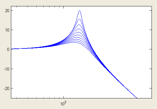
According to that schematic, changing the resonance using only feedback from the first integrator block (what the RES register does) follows this pattern:
http://www.skrasoft.com/blog/blogfiles/chgfeed.png
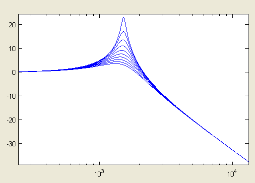
...and changing the resonance using only changes in the external capacitor values follows this pattern:
http://www.skrasoft.com/blog/blogfiles/capchange.png
It just looks like the same standard resonance both ways, with no effect on the filter order (slope).
The bandpass thing, I'm guessing, is the opamps... think of it, rather than one big 2P filter, as a chain of 2 separate 1P filters.
Does this mean that you disagree with that schematic form? Each opamp section in that circuit is either an integrator or amplifier. Treating it as 2 separate 1P filters cascaded would make it an unstable low-pass filter, unless I am misunderstanding you. It is the feedback loops that make it interesting as a filter and allow different modes (HP, BP, LP).
-
It looks like the cutoff depends on the geometric mean of C1 and C2, or sqrt(C1*C2). So if C1 is halved then C2 must be doubled to get the same cutoff frequency.
I don't have a wide range of poly film cap values on hand, only about 5. I made LP sweep files to show the biggest difference I could get. The FC register values were altered to get the same sweep range in both cases.
Case 1: C1=C2=22nF, RES=15
http://www.skrasoft.com/blog/blogfiles/lores.wav
Case 2: C1=1nF, C2=47nF, RES=15
http://www.skrasoft.com/blog/blogfiles/hires.wav
There are some issues that I am still thinking about, though. Increasing the resonance this way should make the band-pass response peak stronger, but it actually dies off on my SID... the band-pass becomes a no-pass.
-
I've been doing filter experiments and found that more resonance is possible from the SID by using *different* values for C1 and C2. A lot more, actually.
Does anyone know how valid the schematic is that's listed here:
http://www.bel.fi/~alankila/c64-sw/
I'm using a 6582. I worked out the circuit equations from that schematic and they're simulating as I would expect in MATLAB. I just want to clarify everything I can before I get too deep into possibly wasted calculations.
Apologies if this is something that's been covered a thousand times before, but I did some searches and didn't find anything.
-
It's working now! There were 3 errors:
1) The address for output volume is 24, not 18. 0x18 is the hex value for 24
2) I had a couple address bits switched
3) The timing for my writing scheme was sketchy. I moved it to an interrupt routine in sync with the clock signal to guarantee the datasheet timing specs are met every time.
It takes about 9 microseconds for my write routine to update the SID... a little slow but not terrible.
-
you may be right re: the extra audio line. It may not be able to provude audio via the cart.
infact, you are PROBABLY right.
Only the Famicom had the connection for audio from a cartridge. Additionally, due to legal constraints by Nintendo America's license agreement, American games had to use Nintendo mappers. All the mappers that included sound hardware were custom designs in the Japanese market (ie Konami's VRC7, the FM-capable chip someone mentioned). Anything brought to the US had to be re-done using only Nintendo chips. That means the extra chips can only be found in imports.
I've been tracking down a couple of the Famicom chips to work with. Recently I found a VRC6. It adds a sawtooth channel plus two more pulse wave channels with EIGHT different duty cycle settings (vs. 3 on the 2A03). Check the soundtrack to Akumajou Densetsu. If you are used to listening to an NES alone, it sounds so much more full and lush mixed with the 2A03. I haven't found or built a circuit to treat it like a soundchip, yet, though.
The other really neat chip is the VRC7, a basic FM chip that was used in LaGrange Point. It ventures into Sega Genesis audio territory. It's so expensive to get ahold of, though, that it makes more sense just to track down similar FM chips from the same period. I am trying to find some YM2413 chips if anyone knows where to look.
-
Hello everyone. I came across this thread while reading about SID programming and thought I might be able to contribute. I've been developing a voltage-controlled synth module that uses the POKEY. Audio demos are on my website at www.skrasoft.com
The four channels are divided into one 8-bit, one 16-bit, and one audio input. The goal was the widest range of sounds possible. It is almost complete, I am just making design changes to tame noise on CV inputs.
I realize my design doesn't fit into the midibox format, but we're both doing musical control of a POKEY. :)
-
we too!!
Sorry i can t help with technical details but i was just wondering: why don t you study the SID application to see what it is needed and where?
Simone
I've been looking at the asm code from the midibox SID micro, but most of it is over my head right now. I program my micro almost completely in C.
-
This is a little bit off-topic, but deals with the SID chip itself.
I am trying to interface a SID 6582 directly with a microcontroller. I think I have everything connected correctly, but I do not have any tested write sequences to use. Basically, what is the simplest set of register writes I can do to get sound? When I first turned the chip on and sent some random data to it, sound came out. To turn on oscillator one, I tried this sequence:
1) Reset all registers to zero (route oscillators straight to output, clear everything)
2) Write anything to address 0
3) Write anything to address 1
4) Write 10000001 to address 4 (select noise wave, turn on gate)
5) Write 11110000 to address 6 (maximum sustain value)
6) Write 00001111 to address 18 (maximum output volume)
7) Wait
...but the result was no output. Is that not a good program to get oscillator 1 going? I am trying to narrow the problem down to being software or hardware.
I have the write pin tied low (it is active low for writing), and toggle the CS pin low for two microseconds then high to write data. It's a poor scheme for timing, but it seemed like it would work for a test run.
Any help/advice would is greatly appreciated.
controlling mb SID with gate/cv, is it possible?
in MIDIbox SID
Posted
To get complete control over the timing and write as quickly as possible, I'm doing it with an FPGA. I couldn't figure out any reasonable microcontroller-based solution with the flexibility and speed I wanted.
When I first ran a SID with a microcontroller, I remember using edges from the SID clock as hardware interrupts to re-synchronize the process on each write. It seemed to work, but I didn't do enough test cases to say for sure. Once I learned the benefits of an FPGA system I stopped messing with the microcontroller setup.