

chrisbob12
-
Posts
24 -
Joined
-
Last visited
Content Type
Profiles
Forums
Blogs
Gallery
Posts posted by chrisbob12
-
-
Hi Sparx, I picked up the sock-puppet meme from audiocommander's web-site: he mentions it as a paradigm for single-handed operation. A white sock gives maximum reflectivity for the IR sensors.
I think we'll work on singing, rather than speech first. How's your speech synth coming along?
Regards, Chris.
-
 Many thanks audiocommander! I've done quite few electronic projects over the years, but this was a real challenge (and it takes so long!).
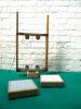
I'm keen to get it cased up. I was going to make something with lots of ply trendy slices (see attachment), but I'm wondering if I should try for something a bit more Luigi Colani (loved his stuff when I was a kid and saw his exhibition in London a few years ago).
Next steps will probably be to check it out with some MIDI running in.
-
Testing, testing...
I got it working about six months ago, and in the lull of a new year, thought it would be good to share. Hope all the link stuf works right. Anyway, more work to do, but very satisfied to have got this far. Maybe I should post this on the projects page, but it felt like closure for this thread.
If only I could get the video to embed properly
Regards, Chris.
-
Hi Audiocommander,
I'd appreciate some advice on configuring the sensor matrix.
Question 1
When I built the sensor matrix, the order in which I connected the sensors was arbitrary, because I was using the sensors to drive a Max patch. Now I'm using it to drive the KII application, they need to map in the correct order to the AINs. I am using AINs 0-3 (J5a on SmashTVs R4 board) which certainly gets results, so I assume that's the correct set of inputs.
One of your earlier posts shows the following diagram.
    BEAM1         BEAM2

      \    +   +     /

       \  /     \  /

        \/       \/

        /\       /\

       /  \     /  \

      /    +   +    \

    BEAM3         BEAM4
Do the beam numbers map beam 1->AIN0, beam 2->AIN1 ... beam 4->AIN3 ?
I have looked through the code, but it is not clear to me.
Question 2
What's your intention with how the beams work? Should the top two beams converge above, below or at the same level of the lower sensors?
Regards, Chris.
-
Thank you!
I enabled midi merge by changing disable to enable in main.c , which seems to work and sends midi inputs to midi out, but not data from the sensor matrix: you can see sensor matrix changes happening in MIOS studio's midi input pane, but it's not transmitted to the output pane - however, MIOS studio keyboard values are transmitted to the output pane.
Regards, Chris.
Heya, nice to hear it's working :thumbsup:
IIRC there's a MIDI Merger setting somewhere that activates MIDI forwarding to the output.
Best,
ac
-
Don't know how, don't know why, but v0.2 now compiles. Perhaps because I closed the Notepad++? Anyway, it all works and I am very pleased. :w00t:
Modifying the code to use a 2x16 LCD and read the AINs for the sensor matrix were both trivially simple due to clear, readable code and good commenting.
It takes me back to Spitalfields four years ago. All credit to Audiocommander's excellent design, coding and documentation. Not to mention the midibox infrastructure and the prodigious amount of work that's gone into the whole body of knowledge.
Naturally, there's still some mopping up:
- Sort out the configuration of the sensors to get the tongue movement associated with the correct sensor postions
- Make nice frames and cases to match others
- Investigate additonal options for routing the controller to send cc or NRPN signals out to a synth
- Investigate the MIDI syncing and note following
Time for a celebratory beer.
And thank you very much to Audiocommander for sharing your great project.
-
After a long weekend away, I took a fresh look at the circuit diagram and put in the power LED (it's not optional) and (ahem) :blush: put in the J2 jumpers.
I now have sound, and I can trigger allophones from MIOS studio. Hurrah!
-
Hi a|x,
Thank you for asking. So far:
v0.1 compiled and loaded (.hex and .syx) into PIC 18F and 16... this morning. It kinda works but no sound. I can get the values characters on the LCD to follow MIOS studio and indeed Max patches for basic MIDI note numbers and the LCD tracks the note names, and the harmonizer listen function on cc37 changes betweeen * and - :I haven't tried any other cc values yet. So I'm reasonably confident about the Core PCB soldering and the code compiling. I'll probably build a Max interface to replicate the MIDI scheme for more testing.
The Speakjet board works fine under Phraselator, as far as I can tell. I haven't tried anything too sophisticated, like sentences, but have put in new words and so forth, with good results. This board is powered by the IIC connection, and I have checked the connections pin to pin on my IIC connection. It always says 'ready' when powered up, occasionally with an extra bonus sound.
So, my plan is to get sound out with v0.1, then figure out how to get v0.2 to compile.
Regards, Chris.
-
The v0.1 application seems to compile OK. There's mention of some fstack error as it does so, but it finishes the process and produces a new hex and syx file, amongst other things. Interesting.
-
No worries, I'm sure it's a foolish little error on my part. At the risk of documenting every step of debugging, I'll just post things I checked.
fixasm.pl has lines 29-31 which are explicitly about eliminating this error:
  # to prevent "Error - section '.registers' can not fit the absolute section. Section '.registers' start = 0x00000000, length=0x00000003"

   # for MIOS it is also required to set the start address to 0x010

   s/^\.registers\tudata_ovr\t0x0000/.registers\tudata_ovr\t0x010/;
I'm not sure what to make of that. Presumably something's bypassing this. I tried changing references to ACSYNC in main.c to ACSyncronizer to look like the other references to files in the package (yes it is pure voodoo on my part) which stopped the infinite loop effect, but threw up a lot of error 112 - I suspect that is not the way to go. Remembered to ctrl-break, and here's the opening lines on the command line when I hit 'make' with unmodified filesC:\kII_026>make gplink -s kII.lkr -m -o kII.hex _output/mios_wrapper.o _output/IIC_SpeakJet.o _o utput/ACSyncronizer.o _output/ACHandTracker.o _output/main.o _output/ACHarmonize r.o _output/ACMidi.o _output/pic18f452.o _output/ACToolbox.o error: different addresses for absolute overlay sections ".registers" ...repeat last line ad infinitum
So a bunch of unlinked .o files, though not for mios_wrapper or pic18f452 (which both have four year old dates in the output directory). Some of it is starting to make sense. A bit :)
Regards, Chris.
-
Hi Michael,
Thanks for your patience and support. Clearly the learning curve continues: command line compiling is new territory for me.
I have installed the tool chain recommended for MidiBox, and also note that PERL is required for KII as well - I have installed Strawberry perl. It all nearly compiles...
The command line dialog threw up a bunch of stuff about the make process before going into an endless repetition of:
error: different addresses for absolute overlay sections ".registers"
So I looked for "registers" in the various files in the application and found that the Perl scripts reassign some of the registers to avoid conflicts. Looking in the .asm files generated by this make, it seems that some parts of ACSynchronizer do not have their registers reassigned, specifically, the following:
FSR1L
POSTDEC1
PREINC1
Maybe I'll need to modify one of the some file to do this, though I have not figured out which one. It seems from previous posts that other people have compiled off these files, so maybe I'm barking up the wrong tree.
Regards, Chris.
-
Ah, I've just seen the demo videos a few pages back. It *is* supposed to be like that. Hey ho. Maybe I should edit out my last posts.
-
A follow up from the previous message:
I focused on the LCD message. I had loaded the v0.2 applications to the PIC16 (with PBrenner) and the MIOS core via MIOS studio. After studying the v0.1 page, I guessed that the ^ (caret - like) characters were the sawtooth settings, associated with the O and E labels. So I loaded up v0.1 and straight away, the LCD display is like the photo on the v0.1 app page, but when I load v0.2 then the LCD shows the characters as described in the previous post; B -SPAN etc.
Is that how it's supposed to be?
(Further detail here: the Smash TV PCB is core R4D)
A note on a bug-like thing - the Icon files in the k11 applications will not extract: I have to deselect them when extracting with WinZip.
Chris.
-
Thanks Michael, I have started following these up. Your recent comments on the sensor matrix (and finally looking in the readme file for the MIOS app have been very helpful, particularly in thinking through the gesture envelope for which the hand controller is designed - and alternatives)
I have moved my copy of the instrument on and things are looking good:
- The SJ board accepts serial control from Phraselator - as far as I can tell I have loaded the PIC 16F... app correctly into the PIC chip
- MIOS studio correctly identifies the core MIDI (one of Smash TV's)
- No funny burning smells
- The SJ only says "ready" once on power up when the core module is connected via IIC
- Sensors present varying voltages at the AIN connections (0-3)
Puzzles:- No sounds coming out yet when I wave my hand in the sensor matrix
- The LCD shows...
B -SPAN
O^E^(and a cursor rectangle)
...after the initial MIOS welcome screen and credits. I've shown ^ (caret) signs although on the display they are more assymetric than that. I suspect that the SPAN is the default harmony mode set and B indicates international.
[*]The 5V regulator is hot (is that the thirsty sensors?)
[*]No response to MIDI notes sent from MIOS studio's keyboard (although my sound card definitely shows MIDI activity)
I'm pretty sure that the LCD message is not right
As far as I can tell from the documentation, SJ does not need to have stuff loaded into EEPROM
Should I be using the .syx file called "release" for the core?
Anyway, early days in a fascinating project - I'm learning a lot. Also very pleased to learn that you named it after a famous automata builder. I have some interest in that area too - my main project in this area is here
www.boutiquerobots.com
Regards, Chris.
Hi Chrisbob,
there are a couple of threads on this forum, where we discussed the implementation of the Sharp IR sensors in great detail. As you already found out, they don't deliver the full 0-5V range, so a scaling is required. Personally I found software scaling much easier than hardware scaling (requiring an amplification circuit and a higher voltage) and thus implemented a good software scaling that works well. Moreover, the scaling can be calibrated which is a lot nicer than hardware scaling.
Please use the search function to find the relevant threads (good keywords are: IR, distance, sensor, sharp, d-beam, ...)
Best,
Michael
-
Darn, I was thinking I could swap it for a beer, in town as well. Glad to hear the LPC17 answers the door - I'd better check it out... maybe my next project.
Hi Chris,
thanks for getting back to me. I managed to get the MAX chip from DigiKey in the US in the end, but don't currently need it, as I went with TKs LPC17-based hardware solution, which is much simpler than ACs documented PIC-based setup. Seems to work pretty well, too!
Thanks again for the offer though,
a|x
-
Hi a|x
Maybe better late than never. I have a spare MAX EEPE chip if you're still interested.
Regards, Chris.
Hi,
just bought a SpeakJet chip, and am looking forward to MIDIBoxing it!
This is a big ask, but could anyone possibly sell me one of the PIC16F88 chips with the SpeakJet firmware already burned onto it? I know there was talk about SmashTV stocking them, but they don't seem to be on his site. Also, I'm having problems tracking down the MAX 232 EEPE. Anyone know of a UK supplier for this item?
a|x
-
Hi Michael,
I apologise for such a long delay in replying to your post in February; life is complicated sometimes.
First of all, thank you very much for your helpful reply and continued support in this thread.
I am on the threshold of connecting it all together and testing software and so forth, and hope to have it working 'soon' and to fascinate a speech and language therapist with it :)
With regard to the Sharp IR sensors, I have done a little more work with the Arduino for a friend's installation and found the following link useful:
http://www.electrotap.com/blog/503
although the thing that made a BIG difference to the noise levels was putting 10K pull-down resistors on the analogue inputs of the Arduino, so I may try that on the MB core's analogue inputs.
Regards Chris.
-
Hi Audiocommander,
Is this thread still live?
I am slowly getting there with this project: it's an interesting learning curve. Anyway, I've got my first Core module built and programmed (MIOS studio is a great help) and have worked through various Brenners to burn my first PIC chips, built the speakjet board (it says "ready") and will soon try and hook them up.
If the thread is still live, I'm interested to hear your experiences with the hand tracker. I have used the Sharp IR sensors through both a Monome's tilt sensor connections and via an Arduino - both into a Max/MSP patch with four oscillators - it's quite fun. As you probably know, these are both based on Atmel chips. I find that the sensing range is less than I expected from the data sheet for the sensors maybe 200mm rather than the 300mm suggested, that the sensor output (as read by the Atmel chips) doesn't go much above about 2/3 maximum, and the signals are quite noisy. Also the response to hand movements is slower than I can move my hand
I realise that the PIC will be different, though I shall be surprised if it is very different. Did you find that the sensors are slow and noisy?
Also, have you considered using the longer-range sensors for larger gestures?
Regards, Chris.
-
I think I've programmed my first PIC chip now. Hurrah! The burner circuit took a bit of debugging (my errors) and I have arrived at Sprut's BrennerNG which not only has the 16F88 in it's sights, but has the nifty burner circuit test features. Speaking as a PIC noob (though long-standing electronic hobbyist) I think I would buy a PIC programmer PCB or module if I did this again.
Now to lay out a board for the speakjet. I can't find the 'vector board' with one pad per hole from Maplin, so I shall either use strip board or try my luck with 'tripad'.
-
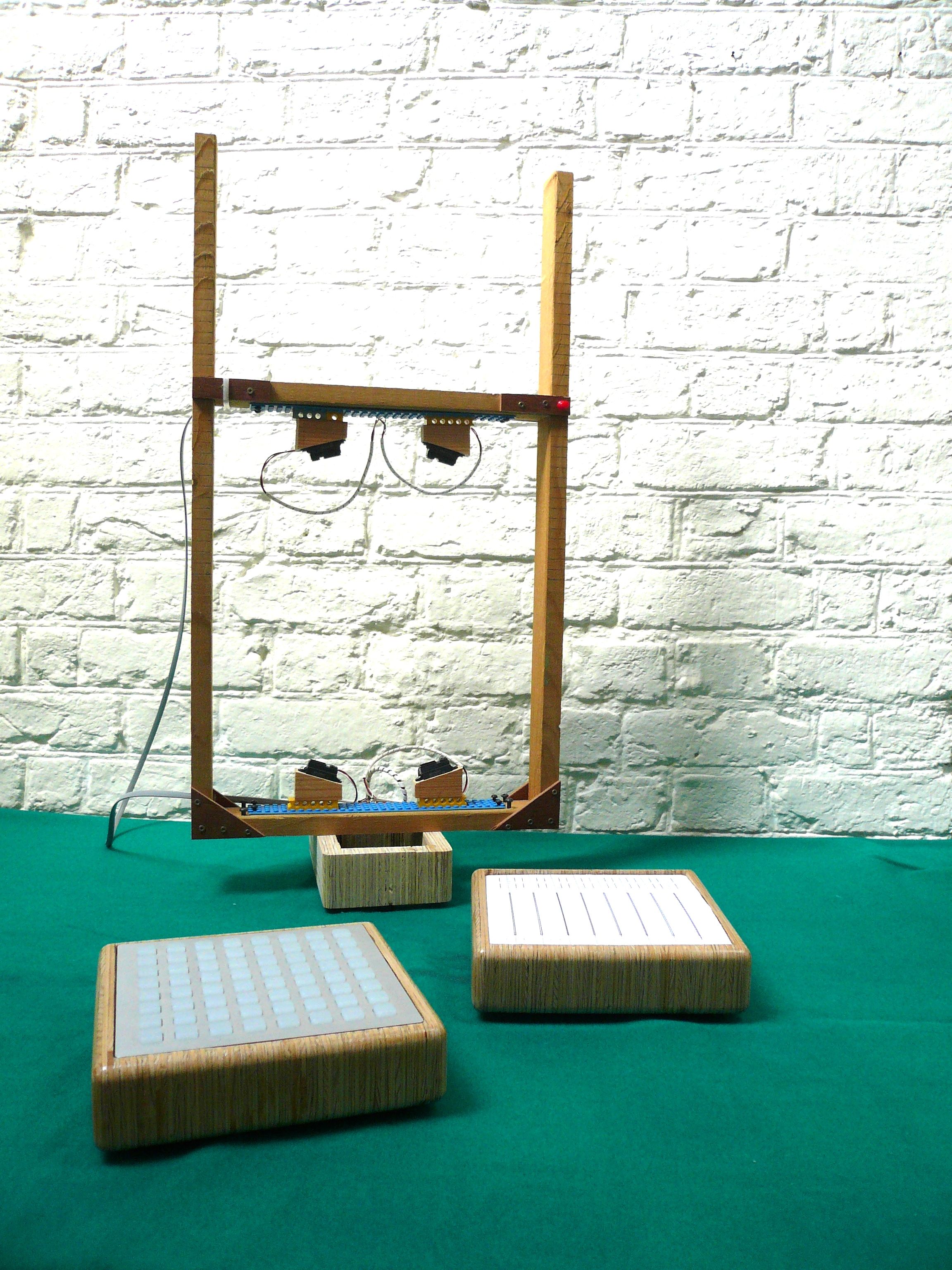
Hello Audio Commander,
I am having a good time with my speakjet project and am glad you have published your work. I have put the gesture frame together first, because I can use it straight away - wired into the analogue inputs of a kit-built monome, it works very nicely. The more I have thought about it, the more interesting the design layout of the sensors is, maybe it was obvious, but I would never have started out with that configuration. As one thinks through other possibilities it becomes apparent that it's a very smart layout.
I have kitted-up the speakjet board including the MAX chip (had to go to the USA for that) and bought spares in case of 'mistakes'. I will release the spares into the wild once all is built.
The next stage has been the MBHP PIC burner, which is all soldered up, running on an original Trace Elliot compressor wall wart, and has so far failed to kill my laptop :) The power supplies seem to work right and present the right voltages to the IC sockets. I have tried a preliminary test with P18 burner software, but the board is not recognised (there is no PIC in yet).
I have two questions:
Which is the best software to connect to MBHP PIC burner? I have loaded Sprut's P18 software on my PC and it certainly looks good, but seems to be for PIC 18xxx only, whereas we are trying to programme a PIC 16. Obviously, it needs the 40-18 pin adaptor and 13.1V, but should I use different software?
Do I need to have the PIC IC mounted in the socket in order for the software to recognise the board?
OK, I found the right page: it's PBrenner37 or 37U - also the board not found message box gives four steps to check, including having the PIC in place.
Regards, Chris.
-
Hi Michael,
I'm making a start on the speakjet/KII project, and have a couple of questions after studying the breadboard wiki page:
1 What is the RS232 PC I/O for? (this is on the speakjet breadboard)
2 Is all the Midibox core needed for making a KII? The Kinetica version looks much simpler than that
PS the point to point wiring looks challenging :o
-
Hi Michael,
The Kinetica exhibit gave a lot of pleasure!
Thank you for pointing me in the right directions - the gesture box diagrams are self-explanatory. I think the sensor arrangement is neat and economical. I think I will give this a try.
Thank you for your help.
Regards, Chris.
-
I saw Speakjet and the gesture box at Kinetica last year and loved it: easily the most absorbing exhibit. I have been searching the internet for gesture sensors to copy the gesture box. My original plan was to hook it up to a monome as part of a mutual instrument, but now I find there's a whole speakjet project and community. Wow! Which way to jump?
I too would be very interested to learn which specific Sharp sensors are used for the gesture box, how many are used and how they're arranged. Of course that may be the magic ingredient ;)
I came to the Sharp IR rangers via Massimo Bandi (of Arduino reknown) and the Acroname Robotics website. I have not yet identified a UK distributor.
All the best.
Speakjet - A PIC ready sound chip?
in MIDIbox User Projects
Posted
I haven't found the chip to be particularly unstable. Maybe it gets stuck once or twice, though it seems to respond to the next bit of hand-waving.