philetaylor
-
Posts
828 -
Joined
-
Last visited
Content Type
Profiles
Forums
Blogs
Gallery
Everything posted by philetaylor
-
Core32 vs. MBHP_CORE_STM32 IO Test
philetaylor replied to Underskor's topic in Testing/Troubleshooting
As the readme.txt for the stm32 troubleshooting app says: I am pretty sure this means DIN modules as well :) Try disconnecting any modules and just run with the CORE32. Having said that, PC15 (Port C, Pin 15) is connected to J16:RC2 which is on the SDCARD/Ethernet port so I would double (and triple) check that there are no shorts. Try a multimeter in continuity mode and check between J16:RC2 and all adjacent pins for any shorts/solder bridges. That failed test suggests that the pin may be shorted to Vdd. Cheers Phil -
Hi. You do realise that you are replying to a 4 year old thread to somebody who hasn't posted in nearly a year ???? I would have said that the likelihood of receiving a favorable response is pretty low :) You could try sending stryd_one a PM as he may get that by email. Cheers Phil
-
Hi. With capacitors, the voltage is it's recommended maximum operating voltage but there is no problem using higher voltage caps on lower voltage circuits. With electrolytics, I tend to use 16v caps for 5-9v circuits and 25v ones for 12v stuff. I never like to run things near their maximum so go with the highest rated voltage one that fits on the PCB. With ceramic, mylar and tantalum ones, these tend to be much smaller anyway. Cheers Phil EDIT: Yes that 7809 looks fine
-
Hi. I would say that both of those problems are likely to be caused by missing or swapped data lines or 2 or more data lines connected together (the most common being a solder bridge causing a short) I would get a multimeter with a continuity buzzer and check that each connection on the core goes to the correct connection on the LCD and check all adjacent connections to make sure there are no shorts. Looking at your first picture, I would also try to clean the pcb with some isopropanol alcohol as you have lots of flux which could be masking a small bridge. I can see what could be at least one bridge (maybe more) and possibly a broken track where the solder mask has been scratched away. Generally with LCD displays, if you get any display (even garbled) then it is likely to be a wiring problem :) Cheers Phil
-
How to kill an STM32 in one easy lesson
philetaylor replied to philetaylor's topic in Testing/Troubleshooting
I know your pain, I suppose the moral of the story is NEVER connect the power until you have checked and re-checked everything...... Anyway I ordered an STM32 today and managed to find a SMD rework station that we bought at work and never used. It is only a cheap hot air one but hopefully still be easier than the alternatives. I will let you know how I get on. I know nILS will probably comment on how easy removing/resolding SMD chips is :whistle: As a backup (and for another 'future' project) I have ordered a couple of replacement CORE32's from SmashTV !!! Cheers Phil -
Farnell sell 45mm 10K linear: http://fr.farnell.com/bourns/pta4543-2015dp-b103/potentiometre-rectiligne-10k-45mm/dp/1688415?Ntt=1688415 Cheers Phil
-
Answer: By not paying attention and don't realise you have turned the CORE32 through 180 degrees then connect your incoming 9v supply to J23 (BOOT0) by mistake! You don't really need to ask how I know this do you :-( Although I disconnected it pretty quickly, I think the damage was already done. The core still boots and 'seems' to work but it wouldn't talk to my MBSEQ control surface and the STM32 seems to get quite hot now...... I put the stm32 troubleshooting app on there and it looks like something is definately blown: Oops. You are welcome to reply with what an idiot I am and any other choice words, it would be nothing that I haven't already called myself tonight! I knew that I would end up having to learn how to desolder SMD chips eventually :) Cheers Phil
-
core32 schematic mistake ?
philetaylor replied to protofuse's topic in MIDIbox Documentation Project
Hi. This should make it a bit clearer, it is a front view like the one on thew CORE32 schematic. Cheers Phil -
core32 schematic mistake ?
philetaylor replied to protofuse's topic in MIDIbox Documentation Project
Hi. No J8/J9 only needs one pull-up resistor on RC as unlike J19 and J16, it only has a single RC line so the last resistor is unused. Cheers Phil -
lol I like that cake, not sure about the age though :( I was driving home today listening to the radio and thinking to myself, "Why don't people just sing on songs anymore". Now where did I leave my pipe and slippers ????? Phil
-
It does now :)
-
That's the story of my life :) Thanks for the cake nILS! Phil
-
Hi. I'm not sure if it is a "glitch" with the forum software but it is my birthday today and the forum says: 0 member(s) have a birthday today No members are celebrating a birthday today sob...... nobody loves me.... :( Phil (yes I have got my date of birth in my profile....)
-
Hi, With your specific question, as the CORE32 uses the 64 pin version of the STM32, there are limited GPIO i/o pins available. As you would need all 16 pins of an available GPIO, I think you would struggle. A quick looks shows that some of the pins used by PA are also shared by the USB port, the LCD interface uses part of PA and some of PC, PB is also used for the boot jumper, there are probably other conflicts and PA, PB and PC are the only fully available GPIO ports on the LQFP64 package. As DIN/DOUT modules have been available for many years, I don't think that direct parallel i/o was much of a consideration when the CORE32 was designed.... One of the other packages (100 or 144 pin) would definitely make this possible (as these expose GPIO D, E, F and G) but would need a new PCB designing..... With regard to reducing the clock speed to talk to DIN/DOUT modules, the SPI driver is DMA based so the lower speed of the SPI transfers shouldn't impact on the overall performance. Cheers Phil
-
MBHP_ETH, MBHP_SDCARD, SSM2044, SSM2164 PCB Bulk Order
philetaylor replied to seppoman's topic in Bulk Orders
Mine arrived this morning, time to warm up the soldering iron.... Another successful bulk order. Thanks seppo :) PHIL -
Hi. No sorry that won't work. For POTs to work in an AIN module, the tracks of all of the POTs must be connected in parallel with the wiper (usually the middle pin) going to the AIN input port, Your PCB has them all connected in series which means you would get some pretty wacky results :) With regard to which way round you connect them, generally it depends on how you want it to work. The left and right pins of a POT are just a simple resistor so if you want a higher voltage to appear at the AIN port when you turn it clockwise then put Vd on the right hand pin, if you want a higher voltage when you turn it anti-clockwise, put Vd on the left hand pin! Cheers Phil
-
C++ Real Time Programming Safety/Style
philetaylor replied to TheAncientOne's topic in MIOS programming (C)
Hi. I read through the JSF programming rules when they were first released and there are definitely some good points but IMHO they are too restrictive in some areas as well, especially forbidding inline macros and #define constants in favour of inline functions and const declarations. This is fine when developing for PC/Mac/Linux with practically unlimited memory but something like MIDIbox projects where RAM is at a premium, precious stack space can be saved by using inline macros and #define'd constants....... However, I think the readability and style sections (especially naming conventions) would be very useful to implement though :) Cheers Phil -
Hi. Hopefully seppoman or somebody else will chime in here as my knowledge of internal workings of MIDIbox SID is pretty bare (practically non-existant)..... For the CORE8, MIOS 1.9g is the latest version of MIOS, I'm not sure where you got MIOS 2.0 from? There is MIOS32 which runs on a different hardware platform (STM32) but there isn't (currently) a released version of MIDIbox SID for MIO32. Unless you mean MIDIbox SID v2? This runs on top of MIOS 1.9g but it does require a PIC18F4685 based CORE8. Cheers Phil
-
Hi. As per The MIDIbox SID Walkthrough each CORE8 can control up to 2 SID modules: Cheers Phil
-
MIOS32 LCD driver: does one exist for ST7565P
philetaylor replied to Duggle's topic in MIOS programming (C)
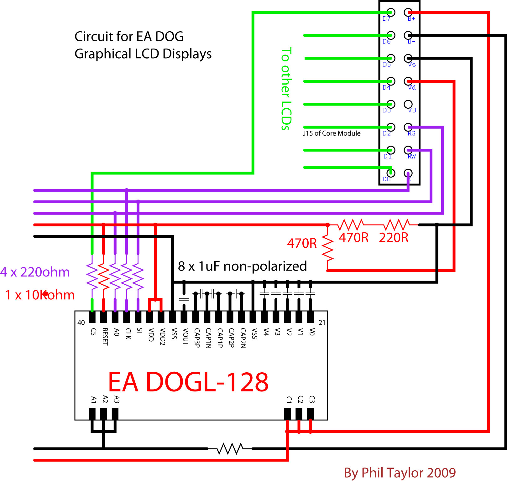
Here is a quick circuit that I "knocked-up" for Ultra some time ago. Please note that the connections to the backlight are backwards.... B+ should go to A1,2,3 and B- to C1,2,3. (I never got round to fixing the diagram!) Also for the CORE32, the 220ohm resistors on the inputs aren't required (as the CORE32 operates at 3.3v). The voltage divider circuit is there to provide 3.3v to the display from Vd (which is 5v on both CORE8 and CORE32) so if your display can take a 5v supply this may not be required either. Cheers Phil
-
MIOS32 LCD driver: does one exist for ST7565P
philetaylor replied to Duggle's topic in MIOS programming (C)
Hi. The ST7565 is pretty well supported by MIOS32 (and MIOS) as it is the controller used by the EA DOGM and DOGL displays! The driver is: http://svnmios.midibox.org/listing.php?repname=svn.mios32&path=%2Ftrunk%2Fmodules%2Fapp_lcd%2Fdog_g%2F The only thing you might need to change is the initialization as your display may be different to the "DOG". The driver uses software SPI (bit-banged) on the standard LCD port. This also allows up to 8 displays to be connected on the same port :) Cheers Phil -
How to port mios32 to other microcontroller?
philetaylor replied to Arkadiuz's topic in MIOS programming (C)
Hi. It really depends on how many faders/buttons you need. If you need 12 or less faders then these can be directly connected to J5A/B/C as per http://svnmios.midibox.org/listing.php?repname=svn.mios32&path=%2Ftrunk%2Fapps%2Ftutorials%2F011_ain%2F However if you need more than 12 then you can use up to 2 MBHP_AIN modules to support up to 64 faders/pots! For buttons, the MBHP_DINX4 module will support up to 32 buttons (digital inputs). These can be daisy-chained to support up to 128 buttons. TK has written lots of examples. There is a fairly complete implementation of MBLC here http://svnmios.midibox.org/listing.php?repname=svn.mios32&path=%2Ftrunk%2Fapps%2Fcontrollers%2Fmidibox_lc_v2%2F and lots of tutorials here http://svnmios.midibox.org/listing.php?repname=svn.mios32&path=%2Ftrunk%2Fapps%2Ftutorials%2F Cheers Phil -
Hi. There isn't any DMX input support currently although it would be fairly easy to add (Eventually it will support RDM which is a 2 way addition to the DMX protocol) If you look at http://svnmios.midibox.org/listing.php?repname=svn.mios32&path=%2Ftrunk%2Fapps%2Fexamples%2Fdmx%2F this is a simple DMX controller using faders to change DMX values. Phil
-
I think the problem may be the space after c:\msys\1.0\bin Try removing it! Phil
-
No it isn't case sensitive. You must quit and restart cmd.exe once you make any changes to the environment variables. You can verify whether you have the correct path by typing "path" in cmd.exe. Thanks Phil