

zgba
-
Posts
56 -
Joined
-
Last visited
Content Type
Profiles
Forums
Blogs
Gallery
Posts posted by zgba
-
-
Look at this schematic http://www.ucapps.de/midibox_sid/mbsid_v2_communication.pdf Have you soldered a resistor and a diode to your core module?
-
MBFM sounds *just* like OPL3, cause it is nothing more like an OPL3 chip with additional hardware and software. Wavetable sequencer has nothing common with wavetable synthesis, it's just a sophisticated tracker-like modulation source that makes possible to change every parameter stepwise. So there's no sample playback available at all.
-
I just bought PIC18F452. I'll program it, replace '4685 with it and check if it helps later. Wish me luck.
-
-
There's an interconnection test app. Upload it and make a test as described in .txt file. Don't wire your LCD in 4bit mode. As far as I knnw it's reserved for 4620's and 4685's. And good luck since my mbfm doesn't make a sound either.
-
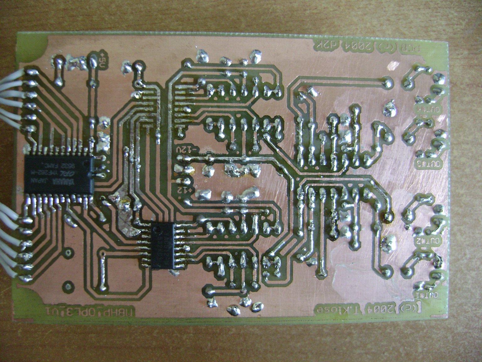
I suggest doing some continuity tests on YAC's and YMF, because it looks like some legs are covered with solder but I am not sure if they're all soldered to the pads. Maybe pour some flux and re-heat them, just to be sure. And read this post that covers running MBFM on PIC18F4620, cause you may have to upload MIOS designed for another PIC to get the whole thing working.
-
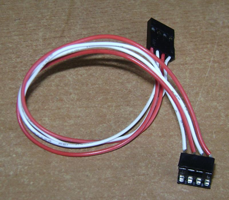
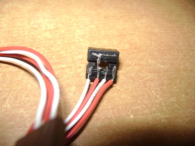
As a temporary solution I soldered 4 short wires to the 8-pin socket with bent legs, and on the other side I mounted a connector. It works like a charm and I can switch it really fast between cores. I think it's the easiest and quickest solution, that doesn't involve soldering your chip directly to the pins on the core module.
-
It sounds more like a heavy digital noise (btw, cool name for a band:), than a testtone, but I can't compare it, cause my mbfm can't speak right now. Better slow down, check all your connections between core and opl3 once more and try again.
-
My core module runs from stabilised PSU. Bridge, 7805 and caps aren't mounted on my pcb, and it works. So it's ok. But in the meantime I installed second YAC512 and swapped YMF262 and nothing changed. I think the problem is in communication between core and OPL. I think my '4685 wants to be replaced with '452...
-
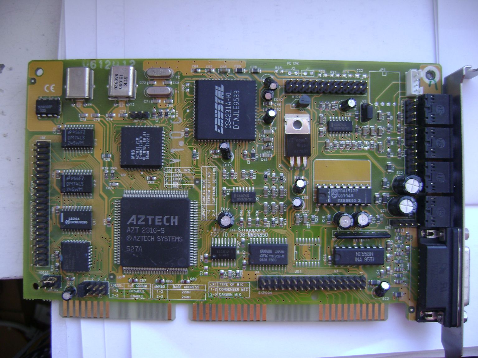
My soundcard arrived today, pretty, isn't it?:) Next step: to desolder everything useful, then back to debugging my OPL3 module.
-
Yesterday I bought another soundcard. I'm waiting for the delivery now and than we'll see if that works.
-
Using 2 PSUs is rather inconvenient. You can do it temporarily, but you should avoid it in your final design. But don't worry you have number of solutions: you can buy another C64 PSU on eBay or something like that really dirt cheap and re-use it without modifications or you can use this 9V PSU you have for +9V and +5V, but then you have to design another PSU and use some heatsinks for 7805 regulator. There are appropriate schematics somewhere in the forum, in the midibox FM section I think.
-
Measuring voltages on unloaded PSU is one thing, on loaded - another. Try to connect another PSU (wallwart or whatever you have with similar voltage) to your circuit and measure the voltages after the bridge and avter voltage regulator. Good luck!
-
Nope, I only connected the LCD in 4bit mode but it was when running '4585 firmware. I saw 'ready' message, interconnection and testtone messages, and some garbage after uploading mbFM software. After switching to '452 firmware I don't use the LCD. I know I should wire it in 8bit mode but I don't want to desolder the wires, cause it's a part of my *working* mbSID. When I find an appropriate 2x40 LCD, I'll connect it in 8bit mode.
-
Try to measure the voltages at your C64's PSU plug. These things are quite old and some of them are faulty. Measure the voltages on the PSU's power plug. It should be +5VDC on pins 3 and 4 (counting clockwise) and ~10-11VAC on pins 1 and 7.
-
When I get this synthie to work, I make a reasonable PSU - 5V @1A and +/-12V @2x500mA. Till then +/-5V must suffice. I just found a guy that might have a tasty soundcard for about 2 Euros. First I'll solder the second YAC and see if it helps. If not - continuity tests once more and maybe replacing YMF. Or maybe you guys have some better ideas? Cheers!
-
@nILS - checking for bridges/cold joints is what I do everyday before I go to sleep:) I do continuity tests and resistance checks. This mess is caused by desoldering wrong placed YAC and reheating joints.
@Imp - It's not a typo. OpAmps can be powered from +/-5V to +/-18V and I have only +/-5V PSU atm.
-
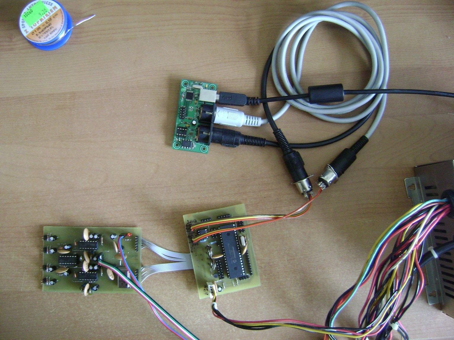
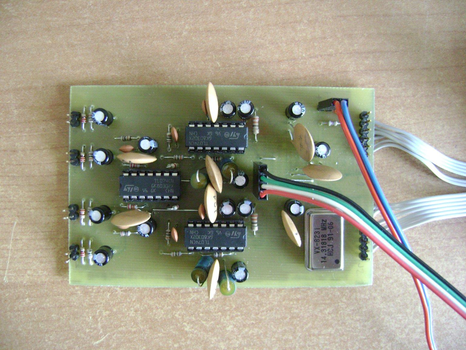
And there are some photos of my setup. I'm using an old PC PSU, that gives +/-5V and +10V/-11V instead od 12, so I don't use it. As you can see I have a brand new GM5 that I'm really proud of. And I know, I have the ugliest 100nF caps in the whole Midibox Community;)
-
Thanks for quick reply! First I trimmed off the cables connecting OPL3 and CORE; now they're <10cm long.
TEST RESULTS:
#1 PIC18F4685 with mios_v1_9f_pic18f4685.hex
CORE connected to +5V
OPL3 connected to +5V
common ground
interconnectrion test:
# 0: Pin J2_1:RS = 5,12V; Pin J2_1:D0 = 4,94V; Pin J2_1:D1 = ~0,9V; Pins J2_2:D2, D3 = 4,94V
# 1: Pin J2_1:A0 = 5,12V; Pins J2_1:D0, D1, D2, D3 = 4,94V
# 2: Pin J2_1:A1 = 5,12V; -//-
# 3: Pin J2_1:WR = 5,12V; -//-
# 4: Pin J2_1:D0 = 4,94V; Pins J2_1:D1, D2, D3 = 4,94V
# 5: Pin J2_1:D1 = 4,94V; Pins J2_1:D0, D2, D3 = 4,94V
# 6: Pin J2_2:D2 = 4,94V; Pins J2_1:D0, D1, D3 = 4,94V
# 7: Pin J2_2:D3 = 4,94V; Pins J2_1:D0, D1, D2 = 4,94V
# 8: Pin J2_2:D4 = 5,12V; Pins J2_1:D0, D1, D2, D3 = 4,94V
# 9: Pin J2_2:D5 = 5,12V; -//-
#10: Pin J2_2:D6 = 5,12V; -//-
#11: Pin J2_2:D7 = 5,12V; -//-
#2 PIC18F4685 with mios_v1_9f_pic18f452.hex
CORE connected to +5V
OPL3 connected to +5V
common ground
interconnectrion test:
# 0: Pin J2_1:RS = 5,12V
# 1: Pin J2_1:A0 = 5,12V
# 2: Pin J2_1:A1 = 5,12V
# 3: Pin J2_1:WR = 5,12V
# 4: Pin J2_1:D0 = 5,12V
# 5: Pin J2_1:D1 = 5,12V
# 6: Pin J2_2:D2 = 5,12V
# 7: Pin J2_2:D3 = 5,12V
# 8: Pin J2_2:D4 = 5,12V
# 9: Pin J2_2:D5 = 5,12V
#10: Pin J2_2:D6 = 5,12V
#11: Pin J2_2:D7 = 5,12V
#3 PIC18F4685 with mios_v1_9f_pic18f452.hex
CORE connected to +5V
OPL3 connected to +5V and +/-5V
common ground
good voltages @ opamp sockets then opamps stuffed
testtone gives no sound
#4 PIC18F4685 with mios_v1_9f_pic18f4685.hex
CORE connected to +5V
OPL3 connected to +5V and +/-5V
common ground
good voltages @ opamp sockets then opamps stuffed
testtone gives no sound
Anything that I can hear is some digital noise when transmitting MIDI data. Conclusion - CORE works, opamps work, or I am wrong? Is it an easy way (I don't have a scope) to see if the digital transmission between YMF and DAC works? Everything I know about these 2 chips is that they were working on the soundcard. Before desoldering of course:)
-
I recently built an OPL3 module. It's connected to CORE running PIC18F4685. After reading some posts I changed the MIOS to '462 version and managed to run the interconnection test, but nothing more. I can't force the FM module to make a sound. When I power up only the core module, the LED on OPL3 lights up (is that normal?). Then I change the modwheel values and I have readouts on corresponding pins, *but* when I switch to pin J2_1:WR, the LED lights brighter, and I have only about 4,95V (my PSU gives about 5,1V). On pins from J2_1:D0 to J2_2:D7 - LED gets brighter and only 4,5V. I tried another PSU (and I know it's a good one, 'cause it works with my mbSID), but no change. I have a bad feeling, that my YMF262 is damaged and I have no spares. Any suggestions?
-
Just got mine:) Indeed, the PCB is really beautiful, but GM5 chip is smaller than I thought... But yesterday I soldered YMF262 and YAC512 chips on a selfmade PCB without soldermask, so I think I can manage it. Anyway, wish me luck! Und natürlich dankeschön Thorsten!
-
Sorry Thorsten, I've been offline for a some time, but already sent a confirmation!
-
My mother said, that the first word I've ever spoken was "knob". Basicaly that's why I'm here. I found uCapps searching for a DIY MIDI controller, but later I found that there are more fun projects than a controller. If you can build it, why won't you do it? So I bought my first C64s last year, ripped the guts, and now I'm a proud owner of a stereo mbSID (well... sort of, only one module connected atm) with a minimal control surface and plans for life:) Great projects, great community!
-
Don't use another hex. You should edit setup_8580.asm , change the line #define DEFAULT_LCD_LINES 2 to #define DEFAULT_LCD_LINES 4 and recompile source code. Don't ask me how. It's all here somewhere:)
Need Help - No Sound and strange Interconnection Test results
in MIDIbox SID
Posted
Stupid question - have you connected both modules to +5V and SID module to +9/12V? It seems that your core works just fine, so there's probably a problem with your SID module and/or with the connection inbetween. And post some photos of your setup (solderside too) if you can. Maybe we could spot something then. Good luck mate.