

grnsky
-
Posts
26 -
Joined
-
Last visited
Never
Content Type
Profiles
Forums
Blogs
Gallery
Posts posted by grnsky
-
-
How exactly does one connect a button to J5 on the CORE? Does one terminal from the button get connected to one of the A0-3 pins and another terminal to the corresponding Vs pin under the A pin?
-
This may sound strange, but I'd really like to connect a button or pot directly to the CORE module if it's at all possible. Is there a way to do this?
For a button, would I just attach one terminal of the button to the Vs and the other terminal to one of the A0-3 (I have a smashTV CORE kit). And for a pot?
The reason I'd like to do this is so that when I turn my CORE on for the first time and upload everything, I'll be able to see if it all works before even connecting other modules. Useful info! But maybe I'm missing something, I mean, I assume those 4 little chips (74HC165) that go in the DIN module serve a necessary purpose, right?
Thanks all in advance!
-
I see. So in other words, you could use a two pole switch to send one message when toggled one way and a different message when toggled the other way? Could you have like one huge encoder, maybe a dial with 50 different things to turn it to (or "poles" i guess) or would it have to have no more than 32 things to turn it to? Or would it have to have no more than 8 things to turn it to since that's how many D's there are on each of my jumpers?
-
Really! Wow, well that's easy enough. I'd still be curious though, how is the encoder different from a button?
Also, for my buttons, I understand I need 'single-pole normally open' buttons...will these arcade push buttons here work?
http://cgi.ebay.com/ws/eBayISAPI.dll?ViewItem&Item=120369534626&Category=13718#ht_590wt_1048
Is it possible to use similar push buttons that actually light up when they are depressed like these?
-
Hi, I was hoping someone might be able to help me here. I finished stuffing my DIN board and am ready for the buttons, but first of all, dumb question, what's the difference between buttons and encoders; when I looked on ucapps.de it offered a PDF on how to connect encoders to the DIN. Is an encoder a pot?
Anyway, I think I want buttons. Now in the buttons PDF on ucapps (http://www.ucapps.de/mbhp/mbhp_dinx4_32buttons.pdf) there are 8 jumpers, but on mine (smashtv DIN kit module) there are only 4 jumpers, each with two rows. Also the ucapps PDF seems to suggest that I ground half the buttons to one Vs and the other half of the buttons to another Vs, utilizing only two of the 8 possible Vs pins.
So I'm confused because I have the smash DIN kit. Do I ground my buttons to the Vs of whatever jumper they are connected to via D-pin? Or do I ground my buttons to only 2 Vs pins as in the ucapps PDF, even though I have a different jumper layout? Or, yet another possibility, do I chain the ground terminals on ALL the buttons and touch it down to just one of the Vs pins, doesn't matter which. OR, yet ANOTHER possibility, do I chain the ground of every 8 buttons (grouped by the jumper they're connected to via D-pin) and touch that down to the Vs pin on the respective jumper?
I hope this question makes sense. However anyone can answer it will I'm sure be super helpful to me. Thank you very much!
-
Hi. I am trying to figure something out...I have a Smash TV CORE that I'm just about done with and will soon be uploading software too. I haven't soldered the MIDI jacks onto the CORE yet though because I'm hoping to get a GM5 soon. Even if I have a GM5 though, will I still need to connect my computer to the CORE directly to upload software, or can you do that through the GM5? Can you even do it through the GM5's USB connection or is there something about MIDI that is different from USB?
How does sending midi signals through USB work anyway...does that "encode" the midi signal into USB language or something or is MIDI signal just some simple data (that indicates channel, on/off, and value) that can go on any cable. What don't I understand? Like, why don't you ever see any firewire midi controllers for example? Sorry, I'm such a newbie!
I guess I'm wondering because ideally I'd like to have a midi controller that has no PSU or midi cable, just USB :)
-
thanks...hmmm...I'll have to find out exactly what the current drain will be of my device. I just read though on the GM5 page on ucapps that the USB via GM5 can provide 500mA. If that doesn't work, I may have to ask you again about the details of how you did that with your GM5.
By the way, I didn't realize that some people already have GM5's - there a waiting list now; were you in on an earlier batch that got sent out? If so, how well did that work out with them distributing it?
-
Great answers, thank you! One more thing...how do I figure out what kind of fuse I need. There's nothing about that on Smash Tv website since it's probably more of an optional thing, but I've ready it's a very good idea. Any suggestions? Does it depend on the size of the PSU? Where do I buy one and do I put it before/after the on-off switch?
-
Hi. I am kind of newbie so sorry if this is a dumb question, but I am building a midibox with the CORE and DIN from SmashTV and I'd really like to be able to use this with my laptop via USB for both power AND midi signal. Is this possible? If so, will I just look for a 2-pin jumper on the GM5 to connect to J1 on the CORE? Will there also have to be another connection to the CORE that transfers the midi data? I'm guessing yes obviously, but how would that work, would I connect the GM5 to where the midi jacks are supposed to go or something like that? I hope this is possible - it would be really cool!
(I already put my name on the GM5 list)
If I am wrong, is there any other way to accomplish this? By the way, according to Smash TV, the J1 on the CORE ought to receive 7-10V and 500ma so I assume that's what I'd need from the GM5 or any other alternative. Thanks!
-
Hi! Thanks to this forum, I have completed the stuffing of my CORE and DIN from Smash TV. But I'm a little confused about the power supply. I read the Connections Table on this site: http://www.avishowtech.com/mbhp/mbhp_coreR4d.html
It says "Either the output of a 7V-10V transformer, or a wall adapter can be used. 500 mA is recommented, especially if a backlit display is used".
1. How do I determine whether I want to go higher or lower within that range of 7V-10V?
2. After I have my power adapter, do I just solder the adapter right to J1 like it says and that's it? Obviously I'll want to put a socket and on/off switch in between, but I mean, do I need the +/- of the power to touch anything else on the board or just J1?
3. If I have no LCD, do I just check it all out with a multimeter and if all is right, assume it's good to go for the software stage?
-
One thing I know - the trimpots are for brightness and contrast for the LCD
-
I am also a noob but I did some calculations and with my basic setup from Smash, 15v 1A was plenty. If you are worried, it is better to go high on the amps (that's what I did).
To get the precise answer, just figure out what you are going to build in terms of options, look at all your components, and then add all your amp draws up. If they are less than 500mA, you'll be fine. If not, you risk damaging something.
As far as I can tell, one of the main variables is the LCD you choose. Different ones can have fairly different mA requirements.
I also have a smash and am a newbie...how exactly do you "add up" the requirements of your components? Right now I have just a DIN, AIN, and CORE. Does that add up to more than 500mA? Is it true that having more mA can't hurt? Do having more mA also mean that you better make sure the Voltage is higher too?
Thanks!
-
-
Hi. This has been asked before but not since 2006 so the forum software suggested that I start a new topic.
I am a newbie well into the soldering of my CORE module that I got from smashTV. All I have left is the two sockets in the middle that hold the PIC and Octocoupler.
Now, does the direction of the sockets matter? I assume the direction of both the PIC and Octocoupler matter greatly. I'm assuming that this is determined by the groove, which must be oriented to look the way the map on smashTV's website looks. But does it matter which direction the socket is placed? Should the grooves line-up same side? Just out of curiousity, why does it actually matter - it seems like the controller can slip in either way...
One side question too if I may... does it matter which direction the 10mhz 49S Crystal goes in?
looks like this -> http://picasaweb.google.com/etbsky/Midibox#5297528984160053954
Thank you!
-
This is slightly off topic, but I'm confused about how the power supply gets connected to the CORE. I have the smashTV kit so I have two small pins sticking out of J1 - are these for the +/- wires from the power supply? This is probably a dumb question, I just wanna be sure so I don't screw things up here. Does anything need to make contact with the big hole on top of the Voltage Regulator at IC3?
By the way, when you say:
"If you're using a backlit display and some LEDs it will probably draw some 500mA."
do you mean that a power supply of a lower mA will cause a completely dark display? What if it is over 500mA - will that cause everything to explode?
Thanks :)
-
Hi. I just have one other question about the capacitors and resistors that came with my CORE kit from SmashTV.
I know the direction matters on the larger capacitors with unequal lengths - longer stick is positive right? How about the other capacitors - the little blue ones that I believe are the 100nF and the little mustard color one that I believe is 330nF and then also the orange 33pF ones. Does the direction matter at ALL on those ones?
Sorry, but I am not an engineer so I really don't know and I'm trying my best here not to screw up. I assume the resistors are all nondirectional (directional does not matter), is this correct?
Thank you!
-
Hi. I'm not an engineer, so I was wondering if someone could help me...
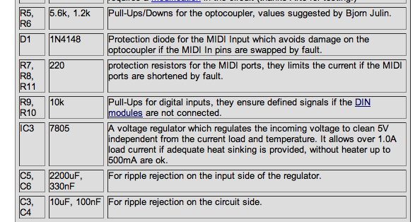
I'm looking at the section of the CORE module components chart on ucapps main page that I've attached a pic of here, and I'm a little confused where in the right two columns there are two values separated by comma.
In the "C3, C4" line for example, it says "10uF, 100uF". This seems to suggest:
C3 is where you put -> 10uF
C4 is where you put -> 100uF
However, on my board (from the kit from Smash TV) C4 has a circle around it that perfectly suggests that green capacitor that says 10uF. Other pairings make more sense the way I'd read it like C5/C6. The shapes line up with that one.
Is this way of reading the chart correct? or does it not go like that? I'd especially love to know which is which for R5/R6 because I really have no intuitive sense for that! :P
Thank you VERY much!!!!!
-
Hi. I am about to put everything into my CORE module and I was just wondering - with the trimpots that are supposed to adjust the LCD contrast and brightness, do I just turn the phillips screw all the way clockwise before installing and then reduce later? Will I have to open up the whole box every time I want to change these parameters?
Shouldn't there be a way to adjust brightness/contrast from the console or somewhere on the outside without having to crack it open every time? I was just wondering - I'm not picky about the display values at all, I mainly just want to have the resistance value at the right place before putting them in. I don't want to do anything wrong.
Thanks!
-
OOOPS! I think you're right. I was looking at the AIN kit parts. Now I am looking at the DIN kit parts I'm pretty sure and there are these little things that look like they could resistor packs. (they're like a little black hot dog with 6A103G written on them and 6 legs on the bottom). When I put these in the board everything made a LOT more sense. WHY would smash TV include all the extra holes then?? And does the resistor pack work just fine - there's DEFINITELY no need for the individual resistors?
Here's what my board looks like with everything stuffed, not soldered yet. Is this right? (see image:)
http://picasaweb.google.com/etbsky/Midibox#5297528954166582082
-
Do you know then, why it seems like I am missing the 36 resistors for my DIN kit? Am I supposed to get those myself or do I not need them? Thanks
-
you only solder the SIL or DIL headers to the PCB. you then use IDC connectors to connect flat ribbon cable to the PCB.
they look like this:

the ribbon cable goes in between the two parts, and then they are crimped together. it then fits onto the SIL or DIL header.
hope this helps.
Are there things like this that are for one row by two holes or one row by four holes? It seems the quick crimping things like this only come in 2x4 or bigger.
-
I'm guessing that all these steps are not needed if you have the SmashTV DIN kit?
-
I'm also on this list. I'm assuming we will be contacted for paypal payment when the minimum is reached and this will communicate the address?
-
Thank you. I do plan to learn by doing. But can you be more specific about how I "map the knobs and buttons the way you want, both on the MB64 and in your application" or give me a link that explains that? I looked in the walk-throughs but they did not actually explain anything about that. This is what I am looking for to complete my understanding of the process.
I opened and toured MIOSStudio - is that what is used to write the application for my controller? Is it possible to just use existing .hex applications? I know how to map midi to functions in LIVE, but how (what's the idea more or less) do you get knobs and buttons to actually emit intelligent midi messages; how does the controller program know what to the display on the LCD, how does it all come alive? I'm not clear on this part of the process. A few sentences on that point would probably set me straight. Sorry I'm so clueless. Thank you.
Re: Power supply, positive or negative connection
in Parts Questions
Posted
How is it that anything within the range of 7-10V is okay? What are the considerations for going higher or lower within that range? If you go to far with current, like say 1.5A, would that be bad in combination with 10v or 7v? If that's a dumb question, don't worry; I know an electrician I can ask, I just thought you might now about it in this context. Thanks**