

Primate
-
Posts
38 -
Joined
-
Last visited
Content Type
Profiles
Forums
Blogs
Gallery
Posts posted by Primate
-
-
I successfully uploaded the bootloader...BUT via COM port (ROM based UART Bootloader method) :frantics:
I wasted three days to get the JTAG going but with no success and I think that the COM port method is the easiest one. First of all less hardware components are required for the job (a COM port connector, four 100nF capacitors and a MAX232). Second and most important the bootloader upload is painless and quick. So all the noobs out there be aware of this.
Never the less tnx to everybody who helped to get my Core going...and now for the fun :D
Best regards,
Primate
-
one thing i remember doing was copy those .cfg files to the same directory so i didnt have any issues with path names..
I have placed all files (parport_lpt1.cfg, STM32F10x.cfg, STM32F10x_upload.script, project.bin) to C:\Program Files\OpenOCD\0.1.0\bin
i have no LED on mine. or did you mean on the core?
I have soldered a LED+resistor between Ucc and GND on the wiggler.
mine wiggler was core powered, but my core was powered with wallwart/plugpack not USB.
check your voltages.
check you're using 74HC244.
check the correct transistor (if not check pinout).
check resistor values.
I power it trough a USB, voltages are 2.9 V, I think that's ok.
I'm using a Phillips 74HC244N, it has a little bit different pins then 74AC244 but I have taken that into account.
Transistor and resistors are ok.
I also doublechecked the wiggler connection.
openocd does still give some error but the bootloader uploads fine.
Do you maybe remember what errors?
Here is what I get when I try to get it going:
OpenOCD 0.1.0.


C:\Program Files\OpenOCD\0.1.0\bin>openocd -f parport_lpt1.cfg -f STM32F10x.cfg

Open On-Chip Debugger 0.1.0 (2009-01-21-21:15) Release

BUGS? Read http://svn.berlios.de/svnroot/repos/openocd/trunk/BUGS

$URL: https://kc8apf@svn.berlios.de/svnroot/repos/openocd/tags/openocd-0.1.0/src/openocd.c $

jtag_speed: 0

Error: missing privileges for direct i/o

Runtime error, file "command.c", line 456:
Open OCD 0.2.0.


C:\Program Files\OpenOCD\0.2.0\bin>openocd -f parport_lpt1.cfg -f STM32F10x.cfg

Open On-Chip Debugger 0.2.0 (2009-07-18-09:50) Release

$URL: http://svn.berlios.de/svnroot/repos/openocd/tags/openocd-0.2.0/src/openocd.c $

For bug reports, read http://svn.berlios.de/svnroot/repos/openocd/trunk/BUGS

parport port = 888

jtag_speed: 0

jtag_nsrst_delay: 500

jtag_ntrst_delay: 500

Error: Translation from khz to jtag_speed not implemented

Error: missing privileges for direct i/o

Runtime error, file "command.c", line 469:
As you can see there are two repetative errorsError: missing privileges for direct i/o Runtime error, file "command.c"
What are the odds that this is windows 7 related?
-
Hi, I have a DIY wiggler made from schematics nILS posted, and a 0.4.0. version of OpenOCD.
I'm stuck and need help. When I run OpenOCD i get this:
C:\Program Files\OpenOCD\0.4.0\bin>openocd -f %MIOS32_PATH%\etc\openocd\interface\parport_lpt1.cfg -f %MIOS32_PATH%\etc\openocd\target\STM32F10x.cfg

Open On-Chip Debugger 0.4.0 (2010-02-22-19:05)

Licensed under GNU GPL v2

For bug reports, read

        http://openocd.berlios.de/doc/doxygen/bugs.html

parport port = 0x378

Runtime error, file "C:\Users\Joc\Desktop\MIDIBox\trunk\etc\openocd\interface\parport_lpt1.cfg", line 11:

    invalid command name "jtag_speed"
I also tried wit 0.2.0. version of OpenOCD but with no luck. I have a feeling it's a minor obstacle but I'm a total noob. Does anybody know where can I find an OpenOCD 0.1.0 installer (for Windows)? Also, does the Core have to be connected to the wiggler at all time?
BTW, is it normal for a LED to lighten up when the wiggler is connected to the parallel port? By the schematics I thought that the wiggler needed a power supply from the STM32 core :unsure:
-
...AIN multiplexer selection lines can be mapped to any free IO pin...
Hi,
I'm also planing to work on a new project and I did some research (btw very very nice work with the tutorials :frantics:) but I didn't know that you can assign free I/O pins to i.e. AINs.
Does this mean that the number of pots, buttons, LEDs or even MIDI IN/OUT ports is limited by the number of free I/O pins (and my programing skills)? If so than this Core32 is more powerful than I thought :drool:
One more question just to make sure, I presume that there is no need to ground the unused pins on the STM32 like the analog input pins on the PIC core, right?
Best regards
-
Hi,
I was also planning to make a new project including a CODEC from TI for line outputs on my MIDIbox. So far I'm going for the PCM1792A (a x2 output, 132dB SNR, 24-bit, 192 kHz Stereo DAC), but I'll have to see how to implement it in the MIDIbox (using STM32 core).
Keep us posted!!! :rolleyes:
-
How is it going with the buttons?
-
Yeah I found that out recently but tnx anyhow.
Maybe I'll post a video if I get the time and the camera ;)
Bye
-
If you don't know the notes try to connect a keyboard to the midi in
hope it helps
cheers
Tnx very much for that...sincerely I didn't think that could be done that way
-
Yeah but on which channel and note??? :P
I didn't develop my own firmware and I don't know the DOUT channel of other accessible firmware...
-
Why?
Btw I'm in the programming phase for my controller so as soon as I figure out the Traktor LED control I'll let you know.
-
Tnx for the info about the vmidibox, I didn't know for that. Although I can't "assign" LEDs to pots (or can I ???) only buttons, and therefore I'll need customized firmware for my controller...
I'm currently using MTE's Traktorizer firmware...you can see from the picture it's not suited for my needs.
-
Yes I did and now I'm trying to make the app which is not going as I planned.
I didn't manage the "Setup and install" for the app development. Also I didn't quite figure out the app development (read program logic). To be honest I really have little time for app development research (because of the other things on my mind) so if you have some directions I'll be glad if you share it with me. I was searching the forum for that matter but it takes a lot of time to get some useful info. I was also wondering how to setup Microsoft Visual Studio C++ for the app development? ???
-
Fond the problem. The power supply, the power connector on the case to be more accurate. It was making a short circuit which apparently effected the PIC long enough to make him go bad.
Anyway tnx to everybody who helped!!!
Regards
-
Yes it works but with a new PIC :P
I only want to determine what went wrong and why so I can prevent it from happening again (and maybe help somebody with a similar problem in the future).
The reboot surely didn't occurred. I also didn't notice anything out of the ordinary on the PC, further more I've tested the controller on a laptop also. One more thing, the LEDs didn't light on startup as usually although I had the voltages as described in the earlier post. The INOUT1 test was OK in the end.
I've also tried to check out the PIC memory via chip burner and I wasn't able to either write or erase the the memory (had an error message) which indicates, to me, that the PIC didn't work properly.
Maybe it was the PC's fault but I somehow doubt it. I'm wondering did maybe the power supply fail on me (read there was not enough current) or was there a short circuit...hmmm
-
Hi guys. Yesterday I was back from a trip and continued detecting what was causing my controller not to work. To make a long story short I couldn't get the controller to work (although the re-installation of the drivers resulted a good INOUT1 TEST) so today I bought a new PIC and guess what...it was the PIC's fault after all.
Everything is OK now (:D) but I still don't know what caused the PIC to malfunction, do you have an idea? I would like, if possible, to prevent and avoid this to happen again.
Regards
-
Now that I have some hints I'll check them all and report what have I done.
Thx once again! ;)
-
Thanks for testing - this simplifies remote diagnosis :)
NO Thorsten thank you for the help!
Ok I've made the test on a Desktop computer and the OUT MONITOR doesn't reflect to the IN MONITOR. Furthermore I have tested the MIDI interface on a laptop and situation there is the same. I'll reinstall the drivers because nothing else comes to my mind how to solve this.
-
First of all thx for the quick response TK ;)
TEST INOUT1
MIDI MONITOR OUT:
timestamp [unknown] | SysEx: F0 00 00 7E 40 01 02 00 00 00 00 00 00 F7
Nothing on MIDI MONITOR IN.
Starting upload of bootloader_v1_2b_pic18f452.hex
Hex file contains code in MIOS range, forcing reboot for upload via 1st level bootloader!
The reboot request will lead to an error acknowledge, please ignore!
Waiting for upload request...
As I understand in this test it is necessary to send a .hex file and see what is on the IN and the OUT monitor? (Sorry but I'm confused after two days of trying to get this running)
-
Hi guys.
I have built my MIDI controller and everything was working fine till yesterday when I powered up the unit and nothing happened. Since then I was trying to solve the problem but unsuccessfully and I really hope you could help me.
So I have a controller with 16 pots, 8 buttons and 32 LEDs connected with the PC via E-MU Xmidi 1x1 USB Interface. As I mentioned everything was fine which makes things more confusing.
Now I can't upload apps (neither the mios and the bootloader) and here is what I get when I try to upload:
Starting upload of app.hex
Sending block #1 00003000-000030FF
there it stops and nothing else happens.
App
timestamp [unknown] | SysEx: F0 00 00 7E 40 00 02 0C 00 00 20 26 7B 65 2F 02 4F 5E 2A 78 16 3D 72 57 41 51 6F 15 3C 0D 1E
79 2B 60 6F 77 4A 5E 0A 5F 3C 55 70 5D 3B 65 2F 04 6F 5E 2A 78 28 7D 72 57 43 13 6F 15 3C 12 3E 79 2B 61 0D 77 4A 5E 07 2F 3C 55
70 40 3B 65 2F 00 1F 5E 2D 78 02 1D 72 6F 40 13 6F 16 7C 01 2E 79 37 61 1A 77 4A 5E 09 4F 3C 55 70 05 7B 65 5F 00 33 5E 2D 78 03
3D 72 6F 40 24 00 00 00 02 20 00 00 00 12 00 00 00 01 10 00 00 00 09 00 00 00 00 48 00 00 00 04 40 00 00 00 24 00 00 00 1F 7F 7F
7F 7F 7F 7F 7F 7F 7F 7F 7F 7F 7F 7F 7F 7F 7F 7F 7F 7F 7F 7F 7F 7F 7F 7F 7F 7F 7F 7F 7F 7F 7F 7F 7F 7F 7F 7F 7F 7F 7F 7F 7F 7F 7F
7F 7F 7F 7F 7F 7F 7F 7F 7F 7F 7F 7F 7F 7F 7F 7F 7F 7F 7F 7F 7F 7F 7F 7F 7F 7F 7F 7F 7F 7F 7F 7F 7F 7F 7F 7F 7F 7F 7F 7F 7F 7F 7F
7F 7F 7F 7F 7F 7F 7F 7F 7F 7F 7F 7F 7F 7F 7F 7F 7F 7F 7F 7F 7F 7F 7F 7F 7F 7F 7F 7F 7F 7F 7F 7F 7F 7F 7F 7F 7F 7F 7F 7F 7F 7F 7F
7F 7F 7F 7F 7F 7F 7F 7F 7F 7F 7F 7F 7F 7F 78 04 F7
MIOS or Bootloadertimestamp [unknown] | SysEx: F0 00 00 7E 40 01 02 00 00 00 00 00 00 F7
I have also troubleshooted the core:
* TEST PROG1: bootstrap loader has been burned successfully before but now I can't do it
* TEST CORE1: done that
* TEST CORE2: /
* TEST CORE3: everything OK (doublechecked)
* TEST CORE4: I have 4.88 V except on the Tx of the PIC18F452 (pin 25) where the voltage is 3.7 V (with the cabel plugged in)
* TEST CORE5: ground OK
* TEST CORE6: OK
* TEST CORE7: OK
* TEST CORE8: OK
* TEST CORE9: OK (doublechecked)
* TEST CORE10: I didn't notice any request messages at all
* TEST CORE11: I'm 99% positive this is OK
* TEST OUT1: LED doesn't flicker
* TEST OUT2: I think this is not required since the controller worked properly with the ground line of MIDI Out port
As I searched the forum I noticed that somebody had a similar issue but since I don't understand German so well I didn't figure out how to solve the problem.
If I had missed out some info let me know and thx for the help!!!
-
Sometimes pays off to invest in some tools and sacrifice a lot of time to get good result.
Well I have the tools (specially because my dad is a repairman) except an laser cutter and the compound miter saw,lol. But to sacrifice some time so I can get a satisfying and precise result isn't a problem for me.
Man you guys do seem to have some shoddy workers. At least I know that in you guys, the next generation of workers will have some pride in their work.
Hang in there, mates :)
LOL but tnx for the support and the belief in us Balkans! :D
-
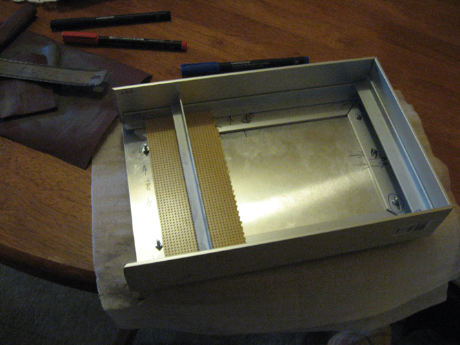
Yesterday I went to cut out the aluminium to the desired dimensions. After the guy has done the cutting job all I have to do is to quote noofny.
"if you want something done right - just don't give it to the retard at the metal yard in Arncliff"
In my case retard from Zagreb but it's amazing that people who do something every day can't do it properly. I attached some pics so you can see what the retard did. There's also a pic of a rough shape of the controller casing.
The PCB is coming on friday and I can't wait to see it. I'll keep you updated.
Cheers.
-
Hey Primate
i made an interesting discover!
I installed Midi Monitor on my Mac to check what traktor sends via MIDI-OUT when you press buttons around
then... i discovered that in the preferences/midi mapping you can set the controls to send midi out (interaction mode: output)
in this way you can choose which note or midi control use to send the midi feedback to the controller.
Works fine!
at this point the work has to be done after the midi-in port of the controller and switch leads on/off depending on midi messages!!!!
hope it helps
ciao
Tnx for the info but I'll have the chance to check it out when Anubis is finished (I hope that will be in 2-3 weeks :P). But of course you will be updated!
-
Does this means tha traktor can control wich led to light on/off depending on what's happening inside the software? If i press the loop button and a loop starts traktor tells the controller to light the loop led??? And then if i press again on the loop button, traktor removes the loop and "tells" the controller to ligh off the llop led??
Is there a way to have midi feedback?
I'm intending to use this feature on my controller so I'll let you know if it works.
-
Ok I think it's time for an update so you don't think I'm jerk*** off around.
I've got all the components (hope you like the knobs in the attachment) including those LEDs that Sasha was talking about and I must say they are nice and so bright you can go blind.
I got some components from Farnell and they didn't charge me for the shipping and the components where delivered the next day I ordered!!! :P
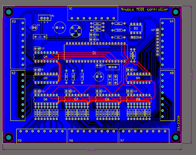
The PCB design is also finished (the PCB itself ought to be done next week).
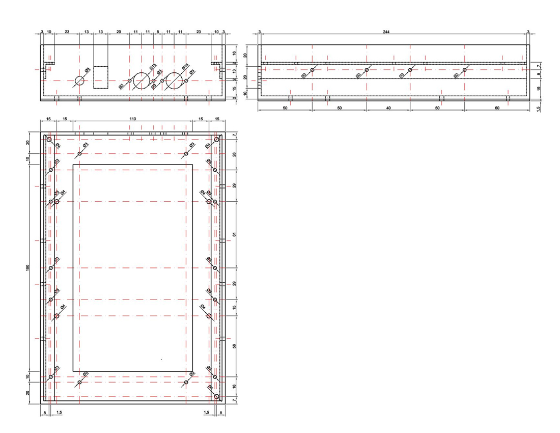
I was intending to get the housing for the controller by ordering it from the workshop but after two weeks of searching for the people who are willing to do it I gave off and decided to make it myself. So I got the "L" shape (corner) aluminium and all I need now is only to cut it in the right places. :D
Here's some pics.
I2S audio DAC
in Design Concepts
Posted · Edited by Primate
Hi,
I'm in the middle of an MIDIBox project and it came to my mind that I could use a I2S compatible audio DAC (TI PCM1754 or PCM1781). I have been reading about the I2S synth on SVN repositories and have some questions:
- LRCIN (WS) -> PA15 (J3:TDI)
- BCKIN (CK) -> PB3 (J3:TDO)
- DIN (SD) -> PB5 (J19:SO)
- SCKI (MCLK) -> PC6 (J15B:E) or PC7 (J15A:E)
If yes, how should the MIOS32_SRIO_SPI (in the mios32_config.h) be defined since neither SPI0 (J16) and SPI1 (J8) are used?
Best regards