protofuse
-
Posts
288 -
Joined
-
Last visited
-
Days Won
1
Content Type
Profiles
Forums
Blogs
Gallery
Everything posted by protofuse
-
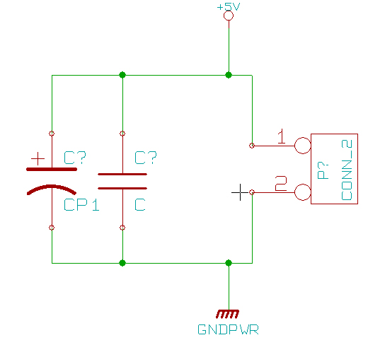
I put the schematic of psu pin J2 part in attachement to this post. values will be the same as in the original schematic. I guess, it is the answer :) (TK, if I found the correct answer, may I win ... a capacitor? or a pretty optocoupler ? :P)
-
hello, I'm using my 5V psu with J2 with a core modified as shown there: http://www.ucapps.de/midibox_lc/midibox_ng_switching_psu.pdf As I planned to make my own PCBs including core/ain/din/dout inside, I'm finishing my kicad schematics and I'm a little bit stuck by the part that concerns J1 & J2 and all the power supply stuff at the bottom right on this schematic: http://www.ucapps.de/mbhp/mbhp_core_v3.pdf if I plan to never use J1 (& and >5v psu) should I remove the rectifier, the uln etc ? should I put them however ? any help would be appreciated :) all the best,
-
I had more success in making my own big pcb for buttons, leds in my project than soldering ... as I can see :P so... I began to calculate how it would cost more I have to (re)buy all components for: 3 AIN 3 DIN 2 DOUT 2 CORES so...
-
ok if i finally decide to make my own midibox modules pcb, i'll share sch too :-)
-
hello, I think, as I'm a bad solderer, I had to make my own double-sided and coated PCB midibox modules in order to avoid bridge, short circuit etc... But another good reason could be to group modules on big pcb. so, the question is: could I get/download .sch of midibox modules? I found brd, but not .sch help would be appreciated :) all the best,
-
hello, in my long way to the protodeck making, I think I killed a capacitor on the Core module with a short circuit that drove too much current... 1st, is it possible ? 2nd can I remove it at least in order to test? (I read on a old post that a guy did it.. but I'd prefer to ask it) 3rd, how can we test capacitor ? help would be appreciated, regards
-
you are right nils, but it was my first day plugged with protodeck and i just was afraid by thé beast and its behaviours ;-) so today is a cold head day... better to check without thinking to drop the whole stuff into thé sea...! i have to check further the core2. probably the short circuit that cause my psu to sleep a bit had just...killed it! the Core 1 is ok upload works, etc Ain & Din are ok :-) dout or code that drives it doesnt light leds matrix correctly i'm using an uln on the first SR like noofny did. the code is : http://code.assembla.com/protodeck/subversion/nodes/protodeck/protodeck_CORE_1/main.c but it doesnt work i suspected my matrix but it is ok after checking it firmware has to respond to midi notes by lighting leds but in order bypass this part, i hardcoded values of ledmatrix storage table...all the same. any ideas or suggestions? http://code.assembla.com/protodeck/subversion/nodes/protodeck/protodeck_CORE_1/main.c
-
hi lylehaze my opto is correctly put on the problematic core! I really don't understand I'll recheck all the solders on the core to track a short circuit I didn't see... fortunately, my other core is ok. mios uploaded. my 2 DIN are ok, but my DOUT behaves strangely (i don't know if it comes from my led matrix or my dout itself: a line seems to be always on, but with a very little luminance... strange) I have to check the ain. I think I had to make my own modules PCB a big pcb with cores, ain, din, dout, double sided, with vynil coat I'm sure my problem comes from bad soldering on the one sided modules &/or wires... grrrrrrrrrrr
-
upload problem on my cores from mike. one core doesn't send anything ( no upload request message) the other one sends is : F0 00 00 7E 40 00 01 F7 but it doesn't seem to receive anything so ... I began the TESTs * TEST PROG1: Trust Mike :) * TEST CORE1: Ok! * TEST CORE2:V3 * TEST CORE3: it doesn't seem to be a problem like this * TEST CORE4: indeed RX is only 1V or around 0.2V instead of 5V .....................! * TEST CORE5: no prob with gnd * TEST CORE6: seems to be ok BUT on out, M+ = M- .................. * TEST CORE7: 1N4148 is correctly placed * TEST CORE8: Ok too for the resistor at midi out * TEST CORE9: ok * TEST CORE10: ok * TEST CORE11: that C5 has contact with the +5V/Ground rails (see also mbhp_4xsid_c64_psu_optimized.pdf)! * TEST OUT1: Ok with a led but lighted up everytime with a little blinking effect * TEST OUT2: ...?! any ideas before I'll burn all :P
-
I'd like to add this to docs, could I? it could be useful for geek like me :) thanks a lot Thorsten. I keep you informed about my project as I'm in a full OpenSource mind and I'd like to spread knowledge as far as possible :)
-
hey experts, I'm in a 2 cores configuration. I want to use a LTC module only for midi in out monitoring. but with the midi link, core1 get MIDI IN from the external world, and core2 send MIDI OUT to the external world... so, how should I wire the LTC in that case ?? indeed, I'd like to monitor the midi that comes from the world inside the box (MIDI IN LED on LTC) and the midi messages that goes to the world (MIDI OUT led on LTC) should I use M+ from J13 (IN) of the core 1 and M+ from J12 (OUT) of the core 2 to feed LTC ? any help would be very appreciated :)
-
yes, still the same thing: make a minimum for my switching psu... only that. My protodeck controller involves arou 96 RGB leds, 2 cores, 2 DOUT, 3 AIN, 3 DIN ... all is here : http://www.julienbayle.net/diy/protodeck/blog/ So probably I don't need a minimum current load at the output of my PSU. the datasheet pdf is here: http://www.farnell.com/datasheets/28497.pdf and mine is the ECM40. for 5V, it is written 0,5 A minimum. perhaps, only with all the midibox modules it involves, it doesn't require any dummy load. I'll try without anything. it could be the first step :)
-
i talked about dummy load only. my controller is the protodeck (you can check it on my website or on google) it is a big controller that probably doesnt requirent a dummy load but...i'd prefer to avoid unwanted switch off ..
-
I exhume an old post. on the psu datasheet, it is written : for 5V, mini current is 0.5A 5/0.5 = 10 ohm. if I put a little led + a 100ohm resistor, I guess it could do the trick I mean, putting a higher value resistor doesn't seem to be a problem.. Am I right?
-
Hi folks, I have just done my pretty Core link between my 2 cores. I only put 2 midi port (IN & OUT..) one on one core, the other on the other or Can I upload my 2 firmware in that configuration ? I saw in the docs that in MIOS Studio there is an ID parameter.. Or should I put 2 other ports each single one on one core ?
-
[Midi Link] any prerequisites to consider ??
protofuse replied to protofuse's topic in Design Concepts
thanks a lot nebula. probably, it doesn't really matter as you said -
hello world :) I almost finished my big controller. I didn't wire midi in, midi out and the midi link between the 2 cores. I'll follow the midi link wiring with "forward point" and "endpoint" attributes: So I have a question: Is there a particular pre-requisite to consider before choosing one core or the other to be the midi in or the midi out ? Probably, there isn't, but I'd prefer to ask to experts :) all the best,
-
thx Janis! I'll do that in ... several minutes. fyi, my project is : http://www.julienbayle.net/diy/protodeck/blog/
-
on this schematic: I understand that if I watch my pots from a front view (soldering pins toward me) I have: Gnd-Value-5V is it right? if it is, I'll just wire like that :P
-
Ok no loop i understood thx nils
-
hello experts, I have to wire my ~100 pots. +5v and Gnd are all common. only one cable between each pot and AINx4 right. I saw that AIN take 5v and Gnd from core, and can "forward" them to pots. BUT for different reason, I'd prefer to wire 5v and Gnd directly from other lines in my circuits. can I do that? or do I have to wire them from AIN ??
-
ok I understood. it NEEDS a dummy load. thanks a lot. I didn't know that... :P
-
...i read before posting,but didnt understand the whole concept ... In my first post i asked about psu spec how could i calculate the right value for my psu ?
-
... Noone sees the line between the fuse and the ground ......? This line contains a led/diode and a resistor... This is about that piece of wire i have doubt
-
I mean the little circuit between GND and +5V .... Under the number (2) on the drawing.