kingnerk
-
Posts
32 -
Joined
-
Last visited
Content Type
Profiles
Forums
Blogs
Gallery
Everything posted by kingnerk
-
Hi, Can you mix and match encoders and buttons on a DIN or is it 1 or another? I cant seem to see any info either way. Cheers Neil
-
Does this mean I have a ground issue?
kingnerk replied to kingnerk's topic in Testing/Troubleshooting
have I grounded this ok then? (assuming Im not connecting an AIN yet) I will try attaching a different power supply to see if that makes any difference too. -
Does this mean I have a ground issue?
kingnerk replied to kingnerk's topic in Testing/Troubleshooting
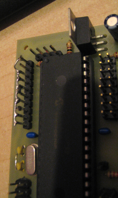
so taking all things into concideration the data was from the ain side so things were not configured right. how were things set up, muxed or un-muxed? correct pins linked to ground? etc Hi, I have attached a pic of how I have grounded the AIN pins on the core. Im not connecting any pots to the core at the moment so I have grounded all the pins but the +5 ( i think thats right?) When i test this its streaming lots of data (until i disabled the AIN in the setup.asm) Setup wise I havent edited anything in the ASM file apart from disabling the AIN board. Thanks for your help

-
Does this mean I have a ground issue?
kingnerk replied to kingnerk's topic in Testing/Troubleshooting
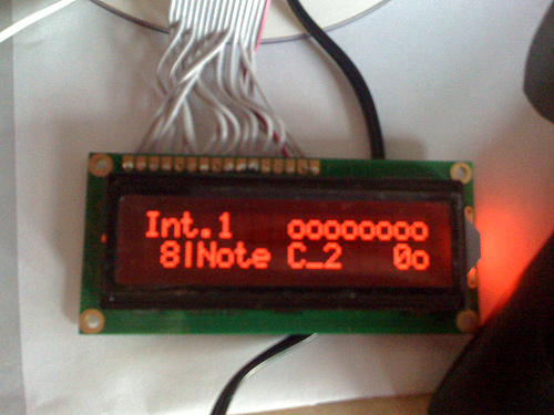
actually i forgot to mention, when its on the display with the button output the far right 'o' flashes on and off. also, on the init pic the left hand side square block flashes on and off. Is it meant to do this? -
Does this mean I have a ground issue?
kingnerk replied to kingnerk's topic in Testing/Troubleshooting
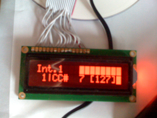
Hi, thanks for getting back to me. Right, I have edited the ASM file, set DIN to 0 instead of 64. Recompiled (wow!) - uploaded it again and now it doesnt appear to be sending lots of data (its not showing lots in MIOS studio and see init.jpg attached to see what it looks like when you boot it up) WHen I press a button on my DIN i now see the following screen (see btnPress.jpg) So, does this look like it was the last of AIN causing all the data to be sent? does this look like my DIN is working ok then? This is the power supply I have btw http://maplin.co.uk/Module.aspx?ModuleNo=46107 Thanks for all your help Neil

-
Does this mean I have a ground issue?
kingnerk replied to kingnerk's topic in Testing/Troubleshooting
Hi, thanks for the replies, I will try disabling the AIN board. Not edited any of the files before so I will see how I get on! also, what is a Switchmode PSU? -
hi, I have built my core, it all works ok. uploaded the mb64 application and it seems to be working ok. I have just connected my DIN, nothing else is connected. When i look at the midi coming in MIOS studio its flashing lots of numbers: like this 00000000024685 ms | [bE 47 00] Channel 15: CC Sound Controller 2 value: 0 00000000024687 ms | [bF 47 00] Channel 16: CC Sound Controller 2 value: 0 00000000024691 ms | [b9 47 01] Channel 10: CC Sound Controller 2 value: 1 00000000024693 ms | [bA 47 02] Channel 11: CC Sound Controller 2 value: 2 00000000024693 ms | [bB 47 03] Channel 12: CC Sound Controller 2 value: 3 00000000024695 ms | [bB 47 05] Channel 12: CC Sound Controller 2 value: 5 00000000024695 ms | [bD 47 06] Channel 14: CC Sound Controller 2 value: 6 00000000024697 ms | [bE 47 07] Channel 15: CC Sound Controller 2 value: 7 00000000024699 ms | [bF 47 09] Channel 16: CC Sound Controller 2 value: 9 00000000024699 ms | [bE 47 02] Channel 15: CC Sound Controller 2 value: 2 00000000024699 ms | [bE 47 00] Channel 15: CC Sound Controller 2 value: 0 00000000024701 ms | [bF 47 01] Channel 16: CC Sound Controller 2 value: 1 00000000024701 ms | [bE 47 01] Channel 15: CC Sound Controller 2 value: 1 00000000024709 ms | [bE 47 00] Channel 15: CC Sound Controller 2 value: 0 00000000024709 ms | [bF 47 00] Channel 16: CC Sound Controller 2 value: 0 00000000024713 ms | [b9 47 00] Channel 10: CC Sound Controller 2 value: 0 00000000024713 ms | [bB 47 02] Channel 12: CC Sound Controller 2 value: 2 00000000024713 ms | [bB 47 05] Channel 12: CC Sound Controller 2 value: 5 00000000024715 ms | [bE 47 08] Channel 15: CC Sound Controller 2 value: 8 00000000024715 ms | [bF 47 08] Channel 16: CC Sound Controller 2 value: 8 I dont have the AIN connected yet, but I have soldered pins 1-8 together and attached that to pin 10 so they should all be earthed. When I click a button I have wired on to #8 on the DIN i get oooooooooooo when I press it, but in MIOS studio it shows that i have pressed it ok 00000000024717 ms | [97 30 7F] Channel 8: Note On C3 velocity: 127 Sorry for rambling. Basically I want to know: a) if its meant to say ooooooooooo when I click a button, and b) is there anything else that would cause the random midi since I have earthed the J5 block? cheers Neil
-
Hi, that looks really cool. Have you come across any alternatives to Ponoko as I live in the UK and the shipping is astronomical! Cheers
-
Hi, I have had a look but only seem to be finding larger prototype companies who dont really look to deal with smaller orders. Im after my jog wheel parts (more info here http://www.midibox.org/forum/index.php/topic,14038.0.html I have found somewhere to get the acrylic discs cut but they were quite expensive, also I would like everything from 1 place so everything lines up Any info/recommendations? Cheers Neil
-
Has anyone used these funky illumintated switches?
kingnerk replied to kingnerk's topic in Parts Questions
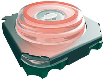
ah, by the looks of things you put an actuator cap on the top of these. So close! -
Hi, I must have spent days looking for switches, and came across these on Conrad. Has anyone used them? They are less than the illuminated multimec ones I was going to get. SMD OVERSQUARE KEY RED ILLUMINATED "This illuminated over square key in SMD connection technology has a small overall height, a pleasant actuator characteristic and an extremely large actuation area" sound really good! I cant get the direct link so go to http://www1.uk.conrad.com and search for SMD OVERSQUARE KEY RED ILLUMINATED has anyone used them? If not I will get some and let you all know what they are like Cheers
-
Building bigger Jog wheels - check my design!
kingnerk replied to kingnerk's topic in Parts Questions
Hi, not sure im going to go the optical encoder route as it will add quite a bit to my cost (as i would need 3!) also im not too bothered about being able to scratch with it, and after playing with a standard encoder in traktor for pitch bend its pretty close to a CDJ pitch bend anyway. The new traktor version also lets you play with the sensitivity of an encoder for pitch bend so it should be all good :) Maybe my next version will use optical encoders ;) -
ok, im stuck. What is the next step for my midibox64 build?
kingnerk replied to kingnerk's topic in MIDIbox HUIs
Ok, so what I have to do is edit the .asm file for my setup (1AIN, 2DIN, 1DOUT) then recompile it again to make a .hex file? cheers -
ok, im stuck. What is the next step for my midibox64 build?
kingnerk replied to kingnerk's topic in MIDIbox HUIs
thanks guys. So im pretty close? Just so im clear, the display acting weird is because I dont have an AIN board attached (and therefore grounded) If i attach the AIN and a few faders and ground the empty pins I should technically have a working midibox? (YAY!) Janis1279: I have opened the .asm file, and i dont really get WHY i need to edit this file? Once I have all my faders etc connected then i will look closer at editing the midibox app. I take it I will have to edit it if I want the display to read out something different when turning a pot for example? Thanks for the help. I just felt I was going in circles and thought I may have to learn C just to use it :) Im pretty nifty with Flash actionscript which is similar to C, but thats the next phase! cheers -
Hi, Ok, so I have built my core and all my modules. I have uploaded MIOS and got the READY status on my LCD. I then downloaded the setup_midibox64.hex file and uploaded that to my core. Was this the right thing to do? Now instead of the ready status it just flicks through a load of numbers constantly and doesnt stop with only the core connected. Is there actually a default midibox 64 app or do i HAVE to install all the C editing software and build my own? Do i have to have all my faders/buttons/pots connected before I can actually tell if all my modules are working or can I just connect 1 module and a few buttons and see it communicating anywhere?? As far as I can tell I just need to fill in the blank: Build modules Upload MIOS ?? play with finished midibox! Sorry for the newb post, i really have spent ages trying to work out whats next, I actually thought the build bit would be the hardest part! If anyone could point me in the right direction i would really appreciate it. Cheers NEil
-
Building bigger Jog wheels - check my design!
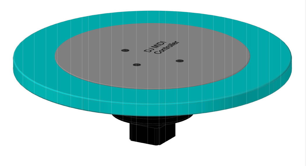
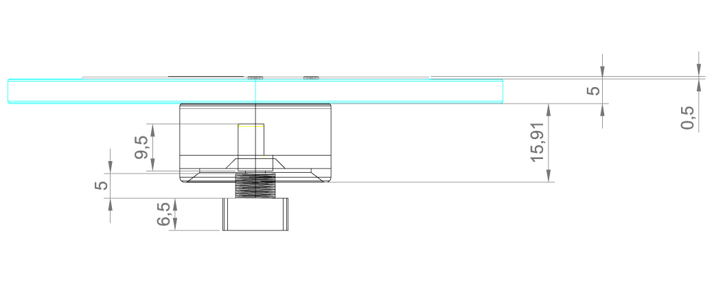
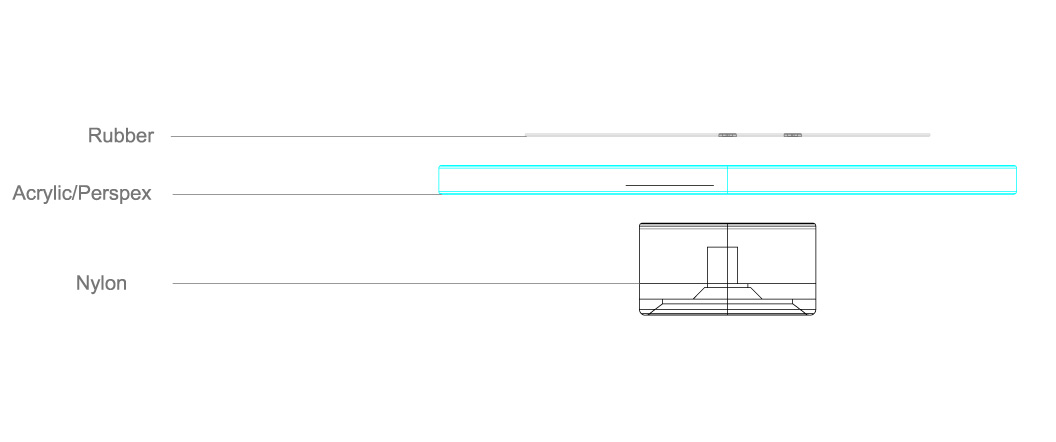
kingnerk replied to kingnerk's topic in Parts Questions
I forgot to mention that the connector will hopefully be made of Nylon, the reason for this is taht its very strong, light and also low friction should the connector come into contact with the panel -
Hi guys, I have been planning my midibox for months now, and i have tweaked and tweaked at the design but he only thing letting me down is the lack of jog wheels available so I'm looking into getting my own built. The design i'm going to "emulate" is the wheel from the Vextax VCI-100 as they are pretty straight forward. the wheel will fit onto a standard D shaft encoder. I reckon the bourns one would be best as its a metal shaft. I want to share my design with you to see if there are any reasons why it wont work. The wheel will consist of 3 parts: the connector that sits on the encoder the platter disc made of acrylic the rubber mat on top. These are then all screwed together I have designed the connector so that if the encoder bends from too much force it the connectors "skirt" will hit the panel and stop it bending any further. Anyway, see the attachments to this post Can anyone see any problems with this design? I dont think you can scratch with encoders anyway, these are more a CDJ style wheel. If i get a good price quoted I may sell extra ones on the bulk buy :)
-
anyone got a large pic of the bottom of the AIN board?
kingnerk replied to kingnerk's topic in MIDIbox HUIs
Hi thanks, I bought the kit from Mikes. From the pics on ucapps it looked like the capacitor was attached to those bridgre wires (which was the bit I didnt get) Ok, so I will just do the bridges on their own, then attach the caps to pins 16 and 8 and then heat shrink them! cheers -
I cant quite get my head round how you attach the caps /wires to the bottom and cant work it out from the diagrams. and the pics on the AIN page are too small :( many thanks!
-
Hi, sorted it by uploading the mios_v1_9f_pic18f452.hex file :) got the ready screen on the LCD. thanks for all your help anyway guys!
-
Hi yes its appearing every 2 seconds so the bootloader is on the pic, just not mios. I have tried the update without mios but I get errors: Error: Received unexpected Upload Request Sending block #1 00000000-000000FF Received error code 05: Write access failed (invalid address range) Im just looking through the forum to see if this has come up before. Cheers
-
Hi, I have just finished my 1st core, I bought a kit from Mikes midishop pre burned PIC, when I connect to the studio my LCD lights up solid, and I get the waiting for upload message (F0 00 00 7E 40 00 01 F7) - I then upload the update_with_old_mios.hex from the 1.9 zip and it says upload successful: Upload of 14080 bytes completed after 10.906s (1.2607739 kb/s) I then turn off the power for a few seconds and reconnect, but the LCD is still solid, and the MIDI IN monitor keeps sending the F0 00 00 7E 40 00 01 F7 Any ideas where Im'm going wrong? Many thanks Neil
-
yeah you are right i will give it a bit more space. Im not actually sure what those are for or whether i need them or not once I have got past the testing phase.
-
Is 16mm the shaft length? I still havent fully worked this out Does this affect the type of knob you can have? Ideally I want some with a centre detent and some without, but which are of the same type/brand so they have the same "feel" Cheers
-
Hi, I have updated the design if anyone wants to have a look. Got all my MB parts yesterday so about to start the soldering :) Let me know your thoughts on the layout.