

LeTran
-
Posts
17 -
Joined
-
Last visited
Content Type
Profiles
Forums
Blogs
Gallery
Posts posted by LeTran
-
-
Depends how small you want to go of course. We use these at work and for the money they are great. Just don't leave them on for hours on end cos they overheat.
http://cpc.farnell.com/roadstar/7310sil/lcd-tv-7/dp/AV18510
ps. site was down for maintenance at time of writing.
-
-
Wow - thanks so much for spotting that !!
Must have been part of the etching process missing off a bit.
I'm going to double check all the connections again.
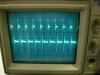
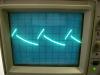
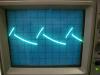
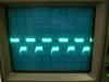
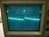
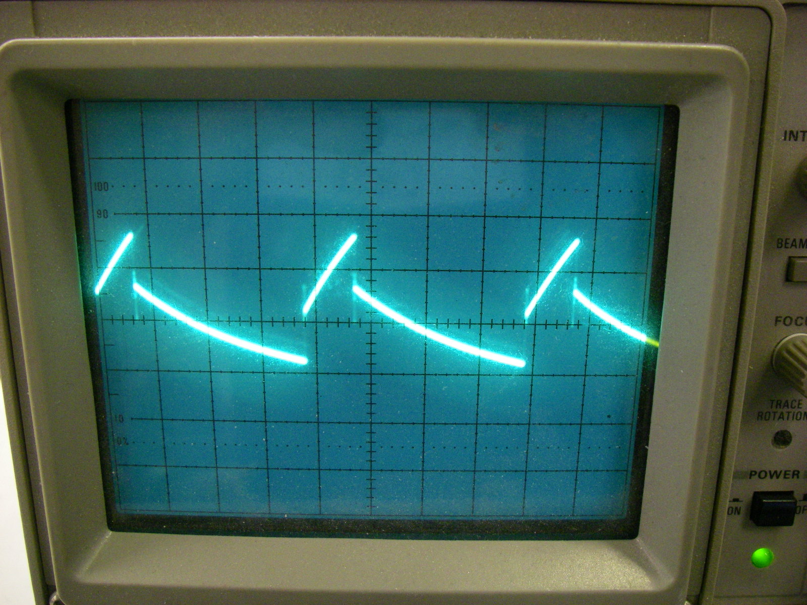
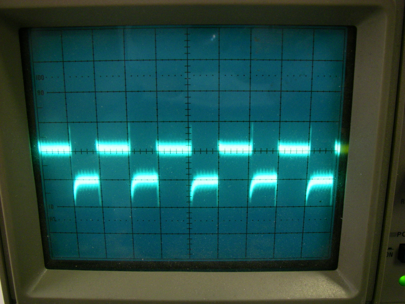
Without the 12v power connected or any of the TL074's in, I've took some pics of my waveforms running the testtone program.
I know that I need the feedback from the opamps for some signals but surely you'd expect something from YAC512 pins 16, 13, 11, 10 ?
Thanks again for all the help so far - I'm determined to get it working and I'll have learnt loads by the time I'm done !
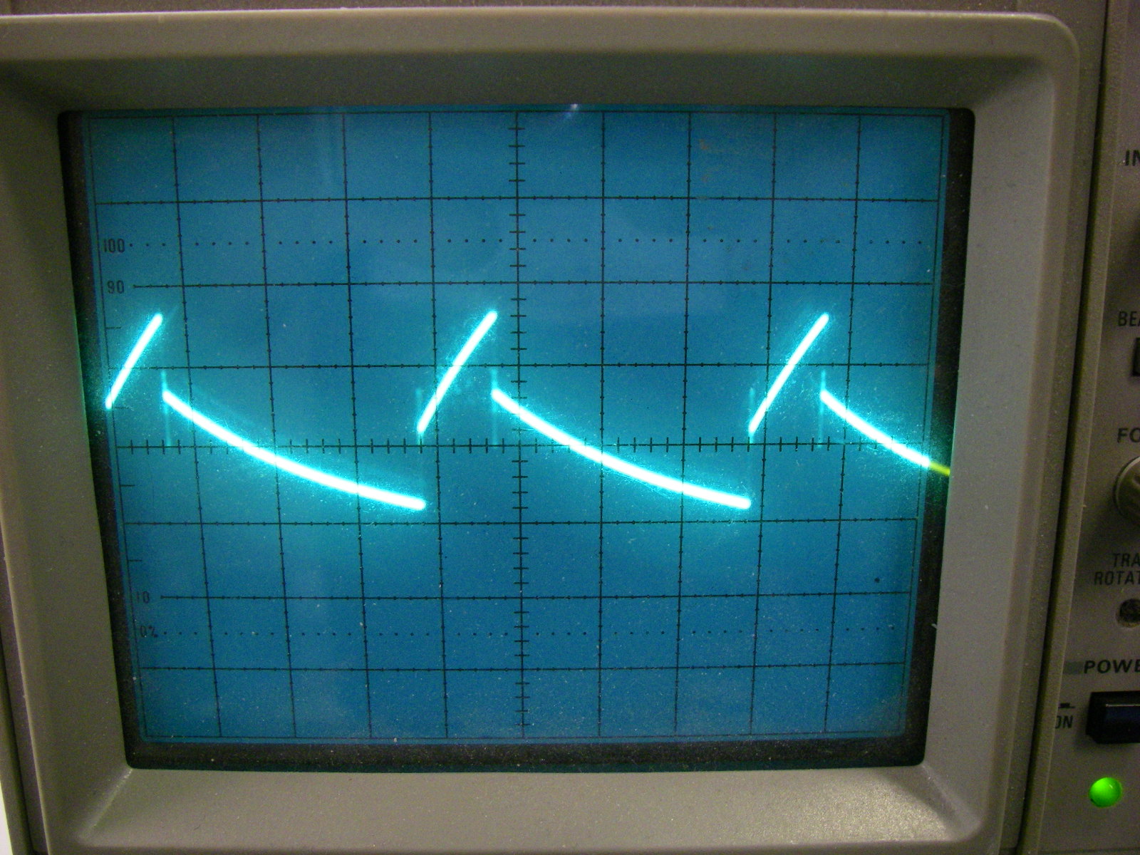
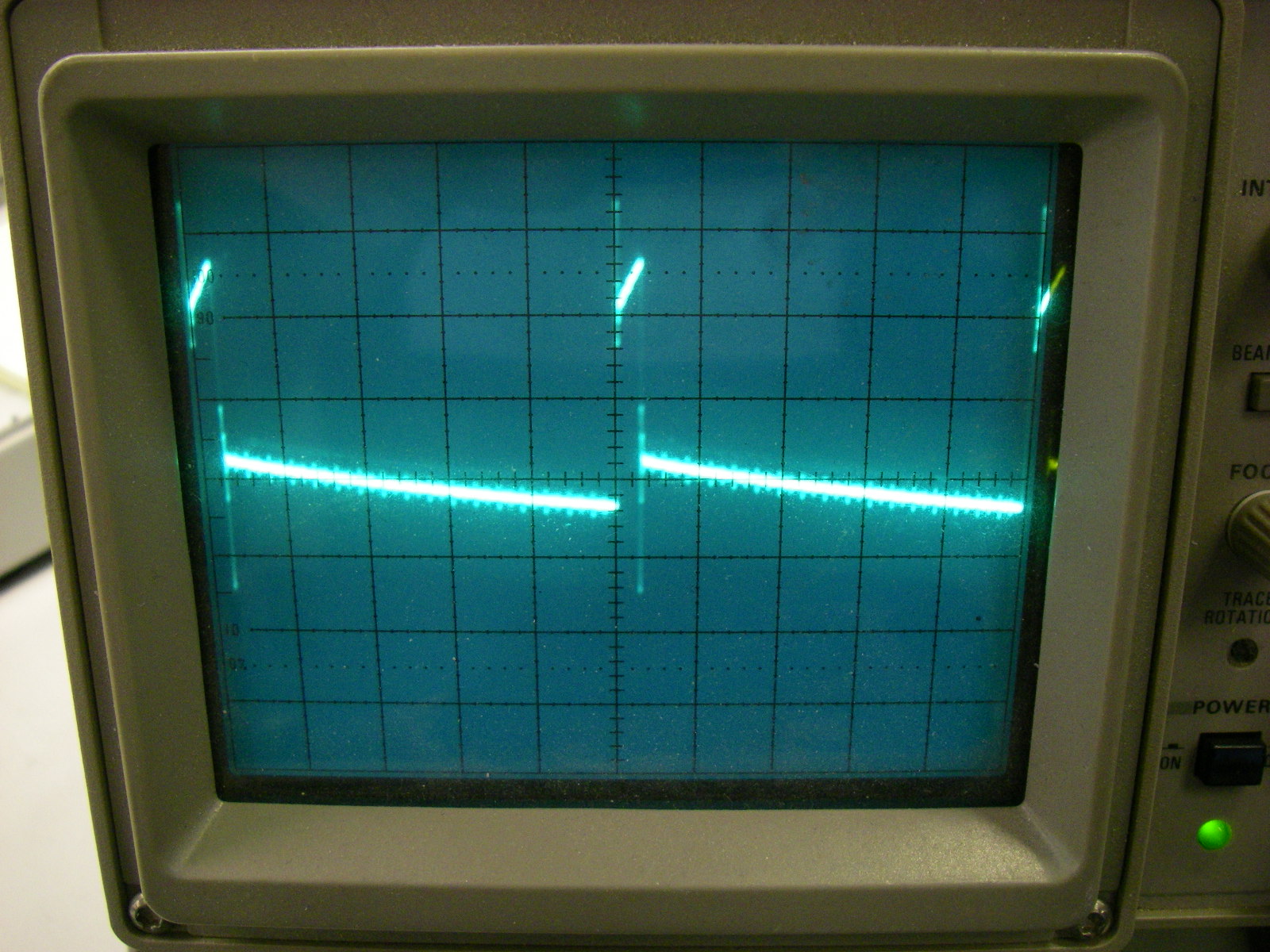
EDIT :- The picture names are wrong. From left to right they are pin 5(clock), pin 7(smp2), pin 8(smp1), pin 12(swin) and pin 4(din).
-
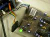
Yes - here's two. the brown wire on the underside was just to eliminate an earth to the 5v side only.
I've made progress !! With a scope i managed to find that my clock freq was dead. Replaced and now the YMF262 gives good clock signals and I can see the output clocks too.
I can trace them into the YAC512 but I'm not getting anything out of it. I presume that the output is now analogue, albeit small.
Could anyone post a pic of what waveforms to get on the YAC512 outputs when running the test tone program ?
I had two others soldered in but I swapped them out for this one to see if the lot had been blown.

-
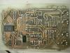
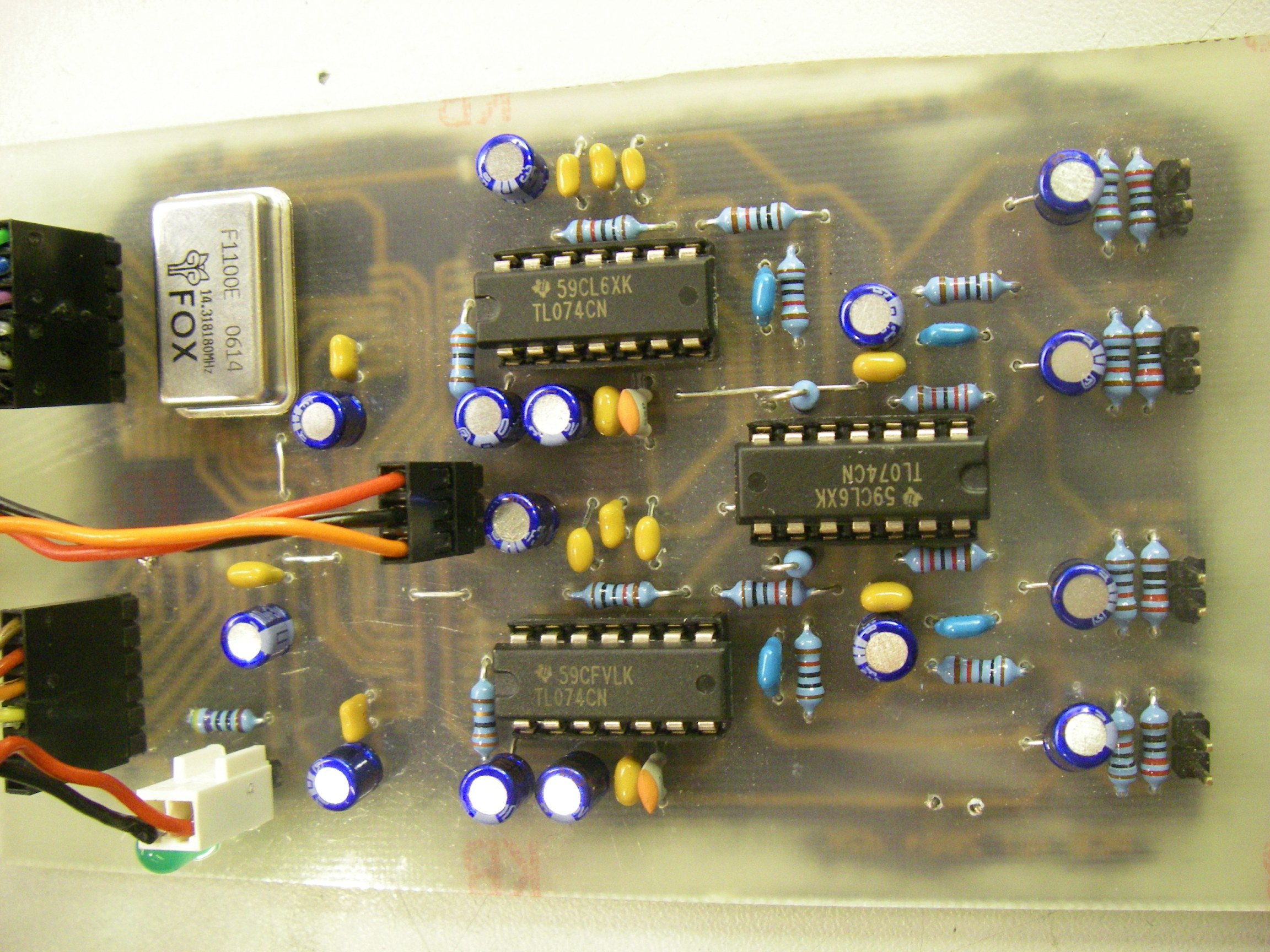
I've just been checking the parts over.
I'm using TL074CN op amps - are these OK ?
-
I've attached a picture of just J2-2 connected. As you can see, the LED is lit.
Not sure what to do now really. I've tried 2 YMF chips.
-
So, does it mean that you are able to control the pins with the virtual MIDI keyboard of MIOS Studio as well?
No that function doesn't work I'm afraid.
With the interconnection test, do you always read 5V on the selected pin, and 0V on all other pins? This would help to exclude a short.Yes.
-
If I remove the power +5v from J1 on the OPL3 board the LED still glows at about half the brightness.
Is this normal ?
I've loaded up the MBFM software and with it set to the default, rhodes piano on CH1 I get +4.09v on pins D2, D4, D5.
Is this correct ?
thanks,
-
I tested the core with MIDI-OX and it works fine.
TK if you do make a change to the interconnections prog then I'll happily test again.
Looks like my problem of dead OPL3 unit could be down to a second dead YMF262 chip ?
I was so careful to get those pins off though !
If anyone else has been down this road and can offer tips to try I'd be grateful. Thanks for the suggestions so far.
-
Tested properly with meter TK but it doesn't work I'm afraid.
However, if you set the modulation wheel to give something other than RS, pressing any key reverts it back to RS.
Hope this helps,
regards,
-
Thanks TK - but I'm afraid it doesn't work.
I can only send modulation data on CH16 (not sure if this is correct or how to change) but pressing keys makes no difference.
The mod wheel still works though.
EDIT: Actually I'm only looking at the LCD display so if that part of the code isn't changed it may still work. I'll test properly.
-
One other question - I'd like to send modulation wheel data [b0 00 00] etc but how can I type that in the MIOS sysex send window ?
The keyboard control is too sensitive.
It's for running the interconnection app.
Thank you,
-
Today I shortened the cables but unfortunately it's made no difference.
Well I say no difference, in fact the LCD won't display it's usual MIOS intro etc. If I uncouple the OPL3 module it displays fine.
Could something on the OPL3 board be the cause ?
I have another YMF262 chip so I'll try swapping it over and see what happens...
UPDATE: Still the same with a new YMF262 chip. Are there any jumpers I need to check ?
-
Yes they do make a slight popping sound. I guess that proves they're OK ?
Thanks for the tip on shortening the cables - I will try that after Christmas and let you know how I get on !
Happy Christmas to all yall.
-
Thank you - they are about 20cm in length on ribbon cable, maybe that's a bit too long? I also fixed up the LCD display and it displays the MIOS version and then states OPL3 testtone generator so I think the core is working properly.
What kind of tests can I do to see if my YMF262 chip is blown or not ?
thanks alot,
-
Hi folks I've been following Midibox for a while now and have just completed my MBFM module :rolleyes:
However, it doesn't work.... :sad:
I have uploaded MIOS successfully to my core and I seem to get favourable responses from MIOS studio. I have uploaded the test tone program which appears to complete successfully. When I listen on the outputs I have nothing.
I have tested all the voltages and they appear fine (I'm doing the 0v linking of the 5v PSU and 12/-12v PSU).
I have put a scope probe on the inputs to the YMF262 and they all appear the same - the same as the clock freq ??!
Are there any steps I can take to narrow down the fault ?
Thanks alot.


Need help troubleshooting MBFM fault
in MIDIbox FM
Posted
Thanks TK - as soon as I sort this issue I'll test the interconnections prog.
I tested the op amps as you suggested and they all work fine so no problems there.
I suspect the YAC512 chips as nothings coming out of them. I have a bulk pack of 25 brand new (unused) ones coming to me soon from USA.
Once it's working I'll no doubt have some spare chips going which I will sell on for a reasonable price. Email me if you're interested.
Thanks once again to all who have helped me. I'll post when it's working :rolleyes: