

UnUnUnium
-
Posts
18 -
Joined
-
Last visited
Content Type
Profiles
Forums
Blogs
Gallery
Posts posted by UnUnUnium
-
-
Hello,
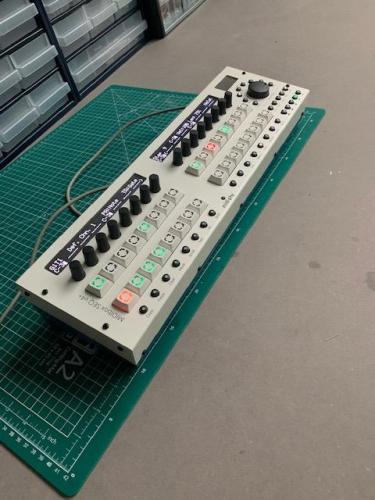
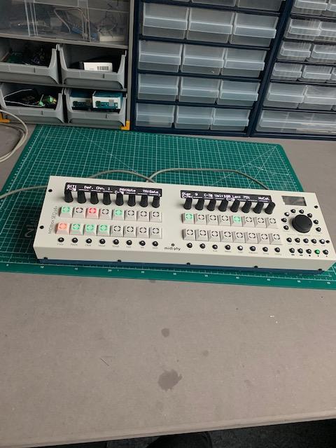
After a few mistakes, I finally finished my build of my Seq V4+
Thank you to Peter/Hawkeye from Midiphy, Michael Menze, and Andy/Latigid On.
It’s working great and I’m finding it very intuitive to work with, though I’ve only just scratched the surface.
All the best,
Jeremy

-
Looks like I got it working! Will do more full testing later but all interface elements are working, and USB Midi is working.
Using the JPA0 Jumper worked perfectly. Uploaded the correct file and popped the config file on the card.
Thanks again Andy :)
All the best,
Jeremy
-
Yes, I think it was the one for the STMF1 core.
I did reboot the core (just pull the power/reset button, yes?) and I closed and reopened MIOS Studio.
Is the correct firmware here? http://ucapps.de/mios32_download.html
JPA0 is on the core board?
Best,
Jeremy
-
Hello,
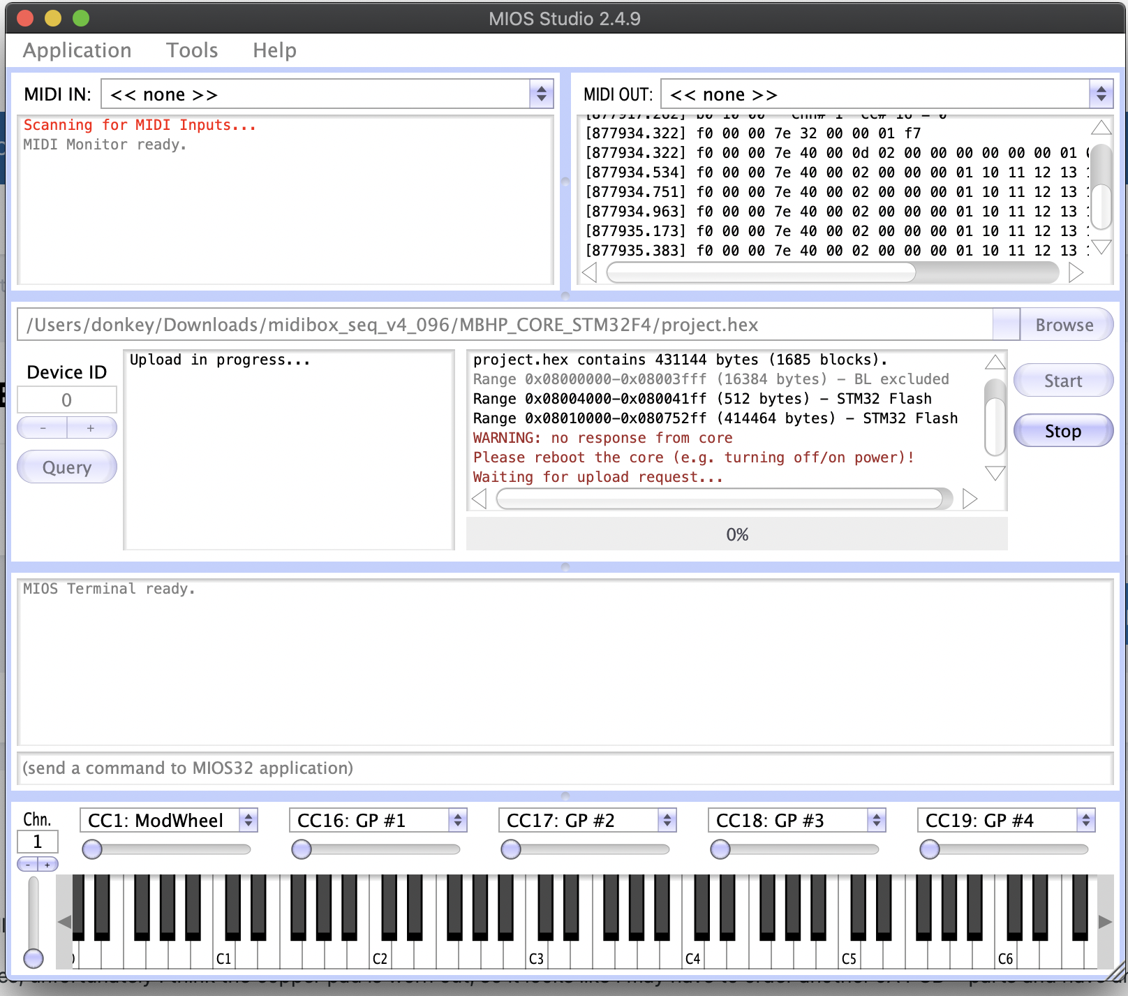
I got to the stage where the firmware was supposed to be uploaded.
All tests (switches, buttons, LEDs) passed perfectly.
Unfortunately, I think I uploaded the wrong firmware and "bricked" the core board - I can't seem to communicate with it via MIOS Studio.
2 questions:
1. If it is in fact bricked, how can I fix it?
2. When I do fix it, can someone link to the firmware for the RH MIDIbox SEQ V4?
I've uploaded a picture showing the message from MIOS - the SEQ V4 has no lights, only the green light on the back pulses momentarily when I plug in power.

-
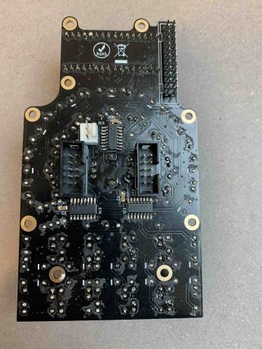
Thank you Andy - I reflowed RN5 and IC20 - it works as expected now!
I think the other two missing in the photo were probably cable related, as I had replaced the cable after taking that photo.
All the best,
Jeremy
-
Apologies - I just realised my above post is the same issue as the previous.
However, I just reflowed IC17 and IC18 and made a new cable - same issue.
Anywhere else to look?
All the best,
Jeremy
-
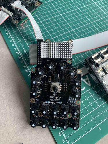
Hello,
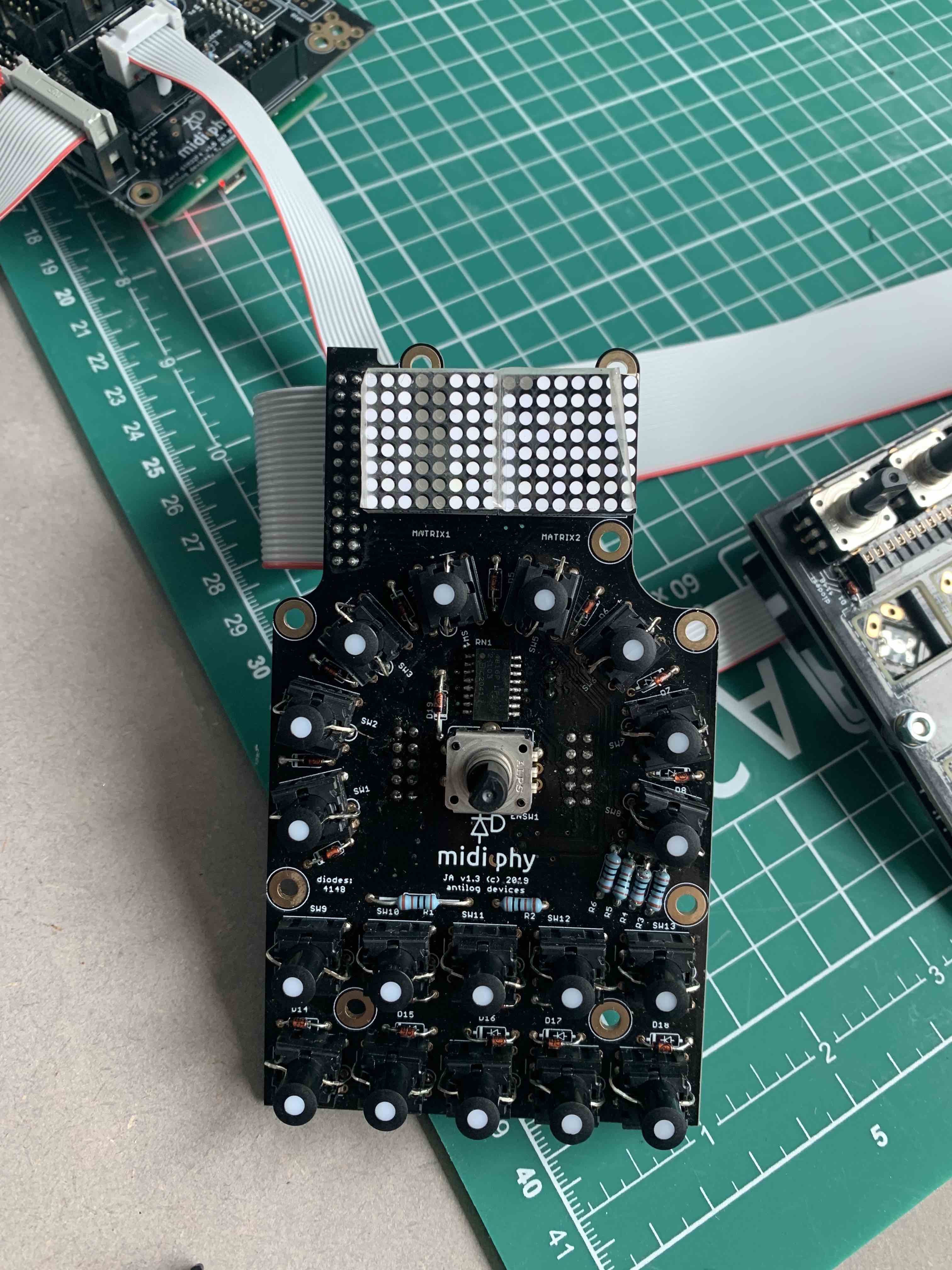
I'm having some trouble with video 2, step 33, 'Building and testing JA Matrix LED cable'.
MIDI CC 16 does move the LED dots, but some of them seem to be missing.
Ive attached a picture - what are the likely culprits here? The matrix itself, the cable, or the shift registers?
All the best, Jeremy
-
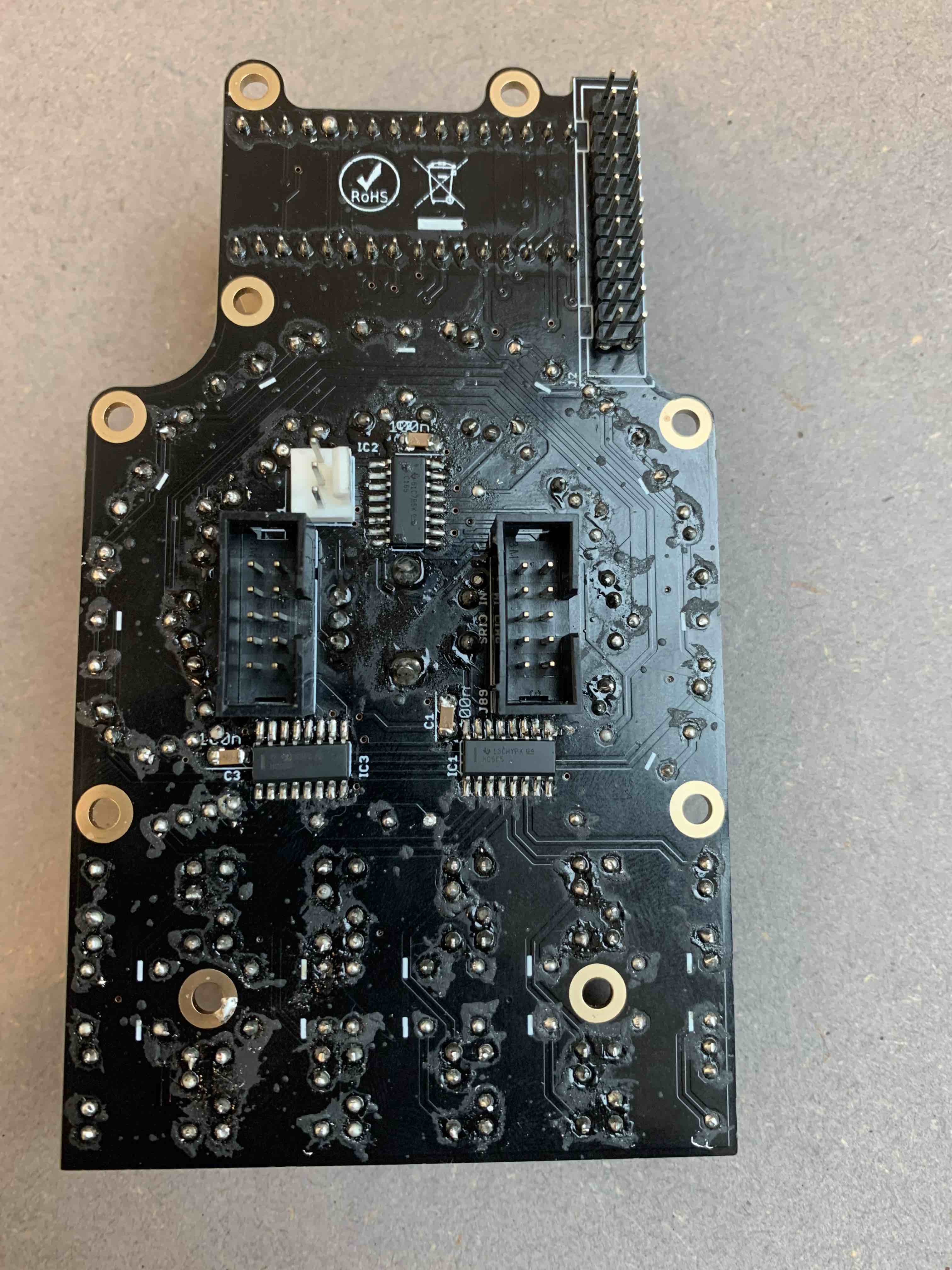
To update, I have tried various fixes to the JA PCB, but to no avail.
I think I will order a new board + parts.
One more question - could my problems have to do with the core board as well, or are they likely to be only the JA PCB?
-
Cool, I've got access to a Mac so I will try to reinstall everything tomorrow. Pretty sure I did close MIOS in between installing the hex files but I'll make absolutely sure to do that next time!
-
Thank you - the bodge option makes sense (jumper wires could do it), and I will probably crack on with building the lemec boards.
One thing I am still confused about is the SEQ_L.NGC situation - I get only 2 MIDI ports (In and out) and no specific NG ports.
load seq_l works though, and I repeated the video many times and I'm not sure what I could have done wrong - the script is on the SD card and installed the hex file from MIOS studio successfully.
-
Thank you both for looking into this.
I've had a look at all my joints, but still no luck. I can look at alternative solder - I also have a flux pen if you would recommend that.
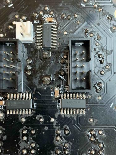
As far as SW 12 goes, unfortunately I think the copper pad is worn out, so it looks like I may have to order another JA PCB + parts and have another go.
Still, it would be good to figure out what went wrong here so I can avoid it next time.
I have installed SEQ_L.NGC, and succesfully loaded seq_l and set debug on.
One thing I noticed however is that 'NG' doesn't show up as a MIDI port in MIOS as it does in the build video. Could this indicate an issue? I'm not sure why it's occurring as I am following the instructions in the video and can successful load seq_l...
LEDs definitely don't have reverse polarity, I checked again, and I was very careful of this in the first place.
As far as the physical issues you mention, the one which I suspect the most is a dodgy ribbon cable - could it be possible that this could prevent the LEDs from lighting up, yet still allow the switches to function?
-
Thank you for your response - here you are! the resistor array is a bit messy after reflow, but I checked for floating and shorted pins through a magnifier and I can't see any.
-
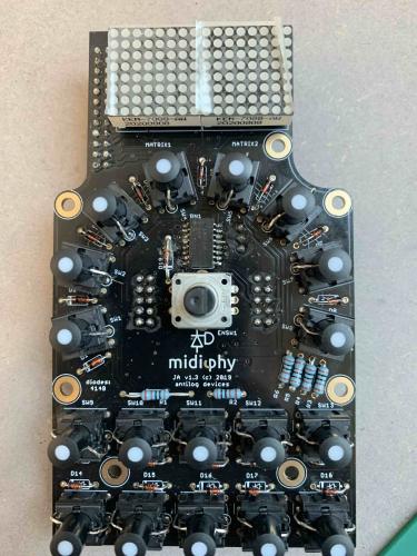
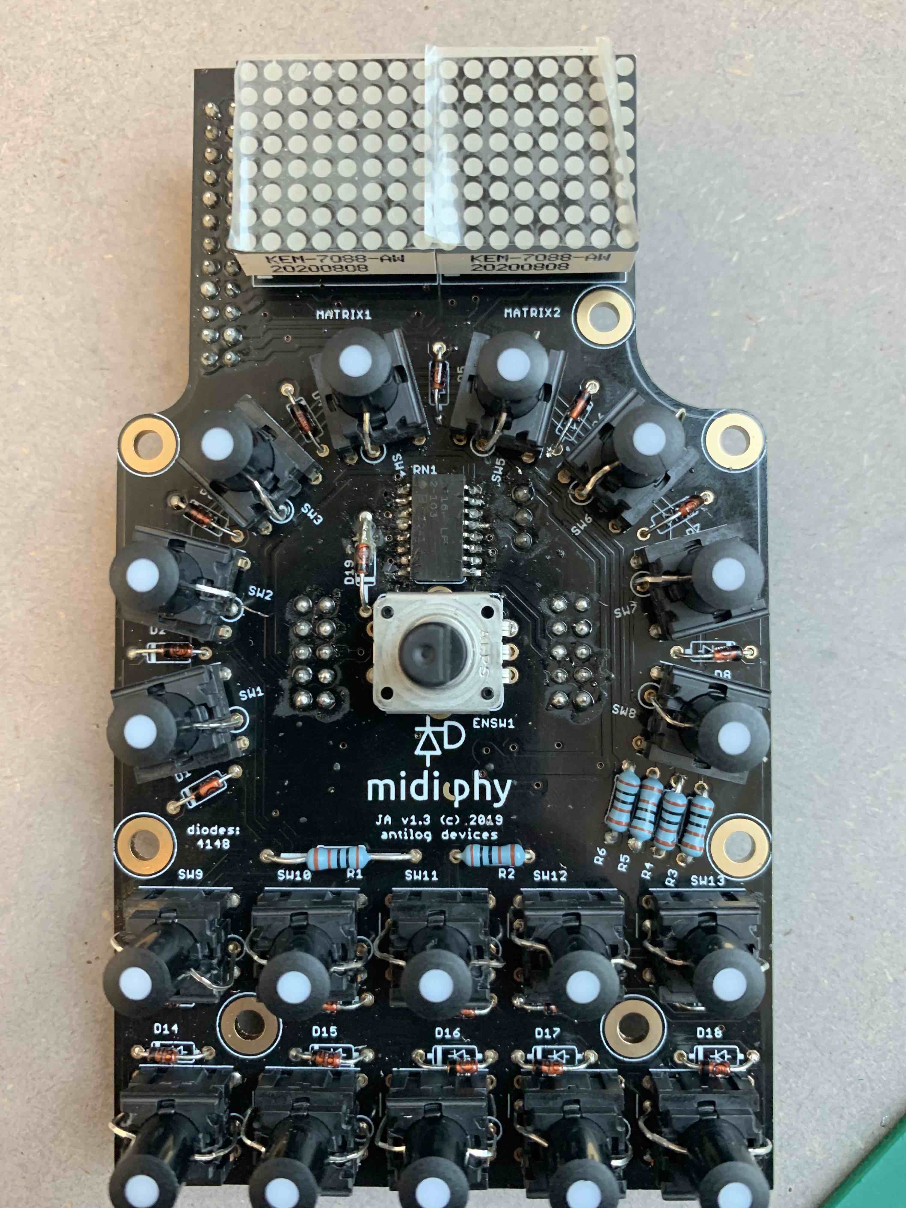
Hello - now I am testing the JA PCB and having 2 problems:
1. All switches show activity in MIOS Studio except for SW 12, which gives no response.
2. None of my LEDs light up when the switch is pressed.
I triple checked LED polarity, part numbers, IC orientation and reflowed everything - still no luck.
Any idea what to look for next?
All the best,
Jeremy
-
Thank you very much - cutting them off with some flush cutters and pumping away the solder eventually worked!
I have connected the USB board up to the computer and confirmed that MIOS Studio can communicate with the board.
Are there any other tests I should run to ensure that I haven't damaged the USB board in the process through heat, or is it safe to say it's fine?
-
Hello,
I am in the middle of building my Midiphy SEQ v4+ and things are going well for the most part.
Unfortunately, I realise that I made a mistake in assembling the USB PCB.
I seem to not to have properly put the metal parts that screw into the case so that they are flush with the PCB - instead, they stick up about 3mm.
I have tried to desolder using a wick/pump but no luck - they are solidly in there.
Everything works on the USB PCB and I'm able to upload the firmware to the core, but I'm aware I will now have a problem when assembling the case of my Seq V4+
Any ideas, or will I have to buy and reassemble the PCB?
-
Great, thank you Peter - It looks like the switches are the same as far as size and orientation and use the standard LEDs, so I'll give it a try and report back :)
All the best,
Jeremy
-
Hello everyone,
I'm going to get started building my Midibox Seq V4+ very soon.
I am building the Midiphy kit.
I read in another forum post that some users are installing black buttons, which I've seen in some of the pictures.
The post I am referring to suggests an alternative button/button cap here:
Questions:
Is this arrangement (5GTH920+1LS096-15.0 instead of 3FTH9+1S11-16.0) still valid with the current PCBs?
Are there any funtional reasons not to make this substitution, or is it an aesthetic choice only?
Best regards,
Jeremy


[S] Midiphy MidiBox Seq V4+ for sale [SOLD]
in Fleamarket
Posted · Edited by UnUnUnium
Sold!
Hello,
I am selling my Midiphy MBSeq v4+. €1400.
Perfect condition, tested extensively but never gigged with, smoke free and dry environment.
Located in Rotterdam, Netherlands for local pickup, otherwise shipping is possible.