

mike
-
Posts
11 -
Joined
-
Last visited
Content Type
Profiles
Forums
Blogs
Gallery
Posts posted by mike
-
-
Look, here's another similar project: http://www.joebrown.org.uk/wp/?p=3124
I've looked better project and I' think there a little error becaude pin 8 of wave connector is cabled in a connector for midi out with ground.
I think must be connected with +5V to give a correct signal to an external midi device.
Correct me if i'm wrong.
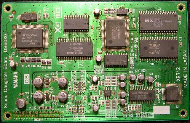
I don't have a DB60XG so discussion it's only academic.
-
Look, here's another similar project: http://www.joebrown.org.uk/wp/?p=3124
Beatiful, but web page say that he's spent less of 30€ (25£). True??
To do my project for only pcb I spent 35€ each (and I've must ordered minimum of two pieces).
So, if is there someone that have a web address to build a board more cheap it's appreciate.
-
Mike
Thanks for the explanation! I've already ordered 6N138, now waiting for it. And, another question - R3 and R4, 220 Ohm both, why not to use just one, e.g. 440 Ohm?
BTW, what current does MIDI current loop use, 20 mA or 10 mA?
reboot
good job! Sounds nice.
I don't understand your question, R3 and R4 are not on the same pin (R3 on pin4 is supply and R4 on pin5 is signal).
Consider that X3 is a Midi Thru port, is not necessary to play, it's for another Midi apparate that use the same played Midi Input.
Current of midi loop I've never measured, but as i mentioned in last post midi signal is elaborate to ZERO Volt; important is frequency of signal, but for technical detail I suggest you a google search.
If you make a search on the web, there are three similar project named:
-Popp Meyer MIDImal (german) 1997
-Elektor 1997
-MistralXG (the best-with USB port and not only) 2009 .......... many thanks to Steve that helped and stimolate me!!
P.S. I've tried CN17 and different 6NXXX and for my basic project are all good, the only difference it's speed of commutation - CN it's more slow, but we are speaking of microseconds so don't worry about this.
Mike.
-
Hello, Mike! a small question regarding your schema: what is the purpose of R5 and C17?
Sorry, i was on holiday until today ..... hope you have resolved
C17 it's a capacitor mounted very near to every supply of active components to avoid change of voltage.
R17 is used to have quick response to signal (that is ZERO volt).
... I've made a little modification/text explanation to my scheme in last post (renamed "Wave_SA_Schema") but core it's the same.
However, for midi input, the same result you can have with other components/scheme
See samples attached
Sorry for my english, i'm italian. And sorry for my explanation, i'm beginner too.
Mike.
-
Does your line-in work as expected?
Today i've made input line circuit but ...... no sound from that input .... sysex? Boh, i've tested some sysex command without result.
-
Does your line-in work as expected?
At this time no, but in these days there it's over 33°C and I don't wish solder so much ...
... meanwhile I've read a lot of Sysex command for enable a/d, and i've made tests for see if instruments are like good (and i like it)
It's born a question: I change correctly instruments by midi-ox thru "instruments panel" that give the command
TIMESTAMP IN PORT STATUS DATA1 DATA2 CHAN NOTE EVENT
0001852F MOX 7 B0 00 00 1 --- CC: Bank MSB
0001852F MOX 7 B0 20 00 1 --- CC: Bank LSB
0001852F MOX 7 C0 38 -- 1 --- PC: 57 Trumpet
.... but not thru XG-Wizard (or XG-Edit) that for the same instrument (trumpet) give the command
TIMESTAMP IN PORT STATUS DATA1 DATA2 CHAN NOTE EVENT
0004F953 1 7 F0 Buffer: 9 Bytes System Exclusive
SYSX: F0 43 10 4C 08 00 07 00 F7
0004F955 1 7 F0 Buffer: 9 Bytes System Exclusive
SYSX: F0 43 10 4C 08 00 01 00 F7
0004F957 1 7 F0 Buffer: 9 Bytes System Exclusive
SYSX: F0 43 10 4C 08 00 02 00 F7
0004F959 1 7 F0 Buffer: 9 Bytes System Exclusive
SYSX: F0 43 10 4C 08 00 03 38 F7
Now i'm a little confused in fact if sysex don't work how i can do command for a/d?
-
Ok,
Thanks
I am already sure for the pinning of the connector but not for the compatibility of the
application with this board.
You have cleared me.
So the creative is the worst of the DBoard :hmm: anyway it is a pity put her in waste
as I own and works well. :thumbsup:
Is there a minimum of schematic for connecting to a core?
I am searching on the forum in this discussion but i found only code file of app.
Effectively it is a MB64 whith midi out connected to midi in of daughter
but if exist a little schematic will be better.
Thanks for any information
best regards
Antix
That's my scheme. It's without usb connection because i use a usb-midi (2.0) cable avcailable on web for 10€
The pins 12 and 16 are used only for 60xg that have line input, so you don't connect (for that I've done a little aggiuntive board connect to SV5 for supply and to SV4 for Input line)
SV3 is a connector to a potentiometer for volume control
At last increase R8 and R9 at 10K to have minor ampli if you want. (for me it's good like scheme but depends from daughter board, with Roland board was too low volume)
I hope is useful for you, good work
Mike
-
Hi,
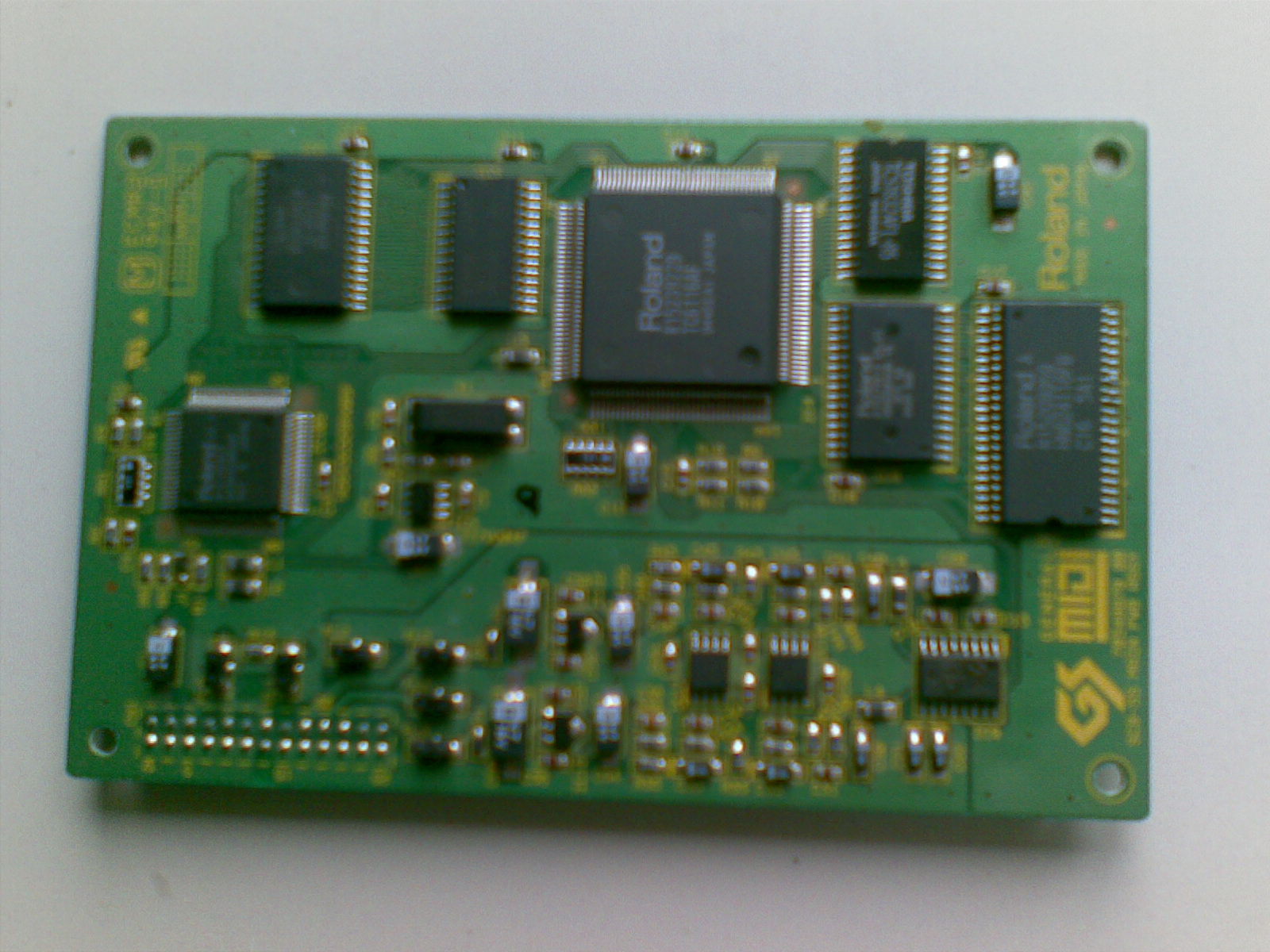
I have a WAVE BLASTER CT1900 with E_mu engine doughterboard.
Can be the same or the application is only for DB50?
regards
Antix
At my knowledge all daughter board like wave blaster have the same connection
In past I had a Creative WaveBlasterI and after a Roland SoundCanvas; now I play with a Nec Xr385
(sound of waveblaster were worst of other)
ROLAND SDBB-55 (SCD-15)
YAMAHA DB50XG / DB60XG
NEC XR385
KORG AG-10
Creative WAVEBLASTER
The difference are the struments and effects.
Mike

-
Yes, one of the pages i've read on the web it's this (and not only-but don't remember what).
I'll try with scheme you suggest.
But ..... do you have a xr385 ? Do you ear something from that input? The istruction (sysex) i've mentioned are correct?
Thanks, Mike.
-
Hi, I have made an adapter board to use Nec XR385 (db60xg clone) as standalone and agter some attempts I could ear good sound from this daughter board.
Reading on the web and looking at card i've seen that there is an A/D converter on it (AK4510) and pin 12 - 16 are used by circuit.
I've tried to connect directly an audio input to these pin and to enable A/D chip by sysex command F0 43 10 49 01 00 00 01 F7 (enable) and F0 43 10 4C 10 01 0B 64 F7 (volume up) but don't works.
After I've found a scheme of an old commercial adapter that use an op-amp (icl7621) like scheme in enclose pdf, it's right?
Is there anyone that have connected - and eared a Line/Mic input from that card?
Thanks at all, Mike.

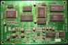
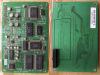
Put Waveblaster daughter board (Yamaha DB50XG) in a box?
in Design Concepts
Posted
Good ..... but it's possible see your project? I'm courious specially regarding your solution noise of nec card.
Thanks, Mike