

Hawkeye
-
Posts
3,636 -
Joined
-
Last visited
-
Days Won
36
Content Type
Profiles
Forums
Blogs
Gallery
Everything posted by Hawkeye
-
@Dimduj and @knochenfabrikyay, great builds, well done! Congrats to #16 and #17! Many greets, Peter
-
Hi Thorsten, also thanks for your consideration from my side! No problem at all, we don't want inefficiencies! Many greets and enjoy the weekend! Peter
-
Same here! :) Had no fan active right from my start in 2010, the SIDs are holding up very nicely! :) (Beware, though, If you have 6581, they run a bit hotter and might require better cooling than the 9V 8580s or 6582s). You could always also install passive heatsinks and drill add a few holes in the case PT-10 bottom for improved airflow - from the MB6582 photo-tutorial: Many greets! Peter
-
Great progress, @pat_00 and @keelhauler! if i count right, you get these serial numbers: pat_00: #14 keelhauler: #15 Very well done, enjoy! Many greets and have a great weekend! Peter
-
Hi Thorsten, here is a question/potential feature request originally asked by @Menzman, but as it came up and i experimented with it a bit, i'd also find it very useful! :) Would it be possible to "glide/slide" on a CC track? A bit like the LFO effect, but between discrete steps, e.g. if a CC value is at 1 on step 4, and at 64 on step 8 and glide is on, would it be possible to output interpolated CCs between these steps? If it is not possible with sub-step precision (like the LFO effect does), that would probably be no problem, as the track could be setup as a "high-res" track with e.g. 256 steps and a fast divider and that would hopefully provide sufficient smoothness. Maybe this is already possible and we never managed to find the feature? :) If not, thanks a lot for considering it and many greets! Peter
-
@otropom Great build! Congrats! The serial number is difficult to say, as not everyone reported back here to properly count :). So, i'd suggest that anyone that built a v4+ can upload a proof of build (poidh :)) here and then claim the next serial number :). Let me recap the history from this thread: SEQ v4+ Serial Numbers (by "visual proof of build" :)) @TK. #1 (first prototype counts) @Hawkeye #2 @rbv2 #3 @Antichambre #4 @Elektruck #5 @CJ55 #6 @Menzman #7 @southpole#8 @Menzman #9 @enveevee#10 @gotkovsky#11 @otropom#12 @niles#13 (pic uploaded in troubleshooting thread) If i did count wrong somewhere, plz correct :) Have a happy weekend, have fun building and many greets! Peter PS: @latigid on is so busy designing new stuff, that he had no time to claim his serial number yet, maybe we should assign him serial number #1.5 as he did most work on this project!
-
Building the MB-6582 Control Surface - Photo Tutorial
Hawkeye replied to Hawkeye's topic in Tips & Tricks
@niles JB-Weld was the way Wilba proposed it, so that's what we did :). It has the advantage of not seeing top-down-screws, and my MB6582 still holds well (after nearly 10 years, omg :)). The height (frontpanel - control surface pcb) was dictated by encoder size mostly, i would guess, it allows to perfectly fit on those "Waldorf" knobs, which are really nice. Nothing much i would change, no - recommend to go for 8580s and omit the fan, go for an OLED or a VFD as a display, a better PSU and a 6.3mm direct mix out, but the rest was just pretty perfect from the start :). Many greets and have fun building it, it's a great synth! Peter -
Hi Phat, moved it to the BLM section, no problem! And you are right, such a big BLM is quite expensive, mostly because there are a lot of parts required. Andy is currently designing a new and improved version for the v4+ (that will also work nicely with the v4 sequencers), but it will still take a bit of time. Have a nice weekend! Many greets, Peter
-
Building the MB-6582 Control Surface - Photo Tutorial
Hawkeye replied to Hawkeye's topic in Tips & Tricks
Bonjour doc007, Hehe, nice name you gave me! :) As the original site is down, i've attached the schem of the PSU to this post - build at your own risk! Happy weekend! Many greets, Peter MB6582-Netzteil.pdf -
Probably @latigid on can help you out way more than i can... but i just looked up the AOUT_NG schem and it seems analog ground can be tied to digital ground (see middle of the schem), maybe by a jumper? If that is the case, i think the grounds should be all tied down together and nothing is floating, which might cause problems. We are using the AOUT (not NG) module, so i don't really know much about the NG. Two more questions: do you use a DOUT module for the triggers? I think, if an analog out would be used for that digital purpose, the DAC might "overshoot" or ring or might not be quick enough, but that is wild speculation. Do you have access to a scope, so you can see the trigger output waveform? Many greets and have a nice weekend! Peter
-
New eurorack modules from midiphy - preview
Hawkeye commented on Hawkeye's gallery image in Members Gallery
 ps: the panel graphics will still be updated slightly for the final version - like the v4+ case, Hallik Engineering will provide them and we can't wait to have them in hands :).
 -
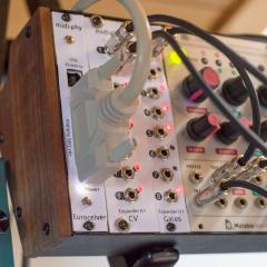
Hola, just tested the new dedicated midiphy eurorack modules, that are in the works - while i don't have a big modular setup, i measured and tested gate and trigger outs and had no issues (tested triggering the "Freeze" and the "Trig" functions on a MI Clouds and also measured signal outputs with a scope). Therefore, I would also expect maybe a common ground problem on your side? Have you grounded the external PSU and the LineDriver Receiver to the modular/rack common ground? The new euroceiver module (left in the pic below, which still uses handmade paper/epoxy panels for fit-testing) has a built-in voltage regulator, that allows generating the required 5v from the +12V modular rail, which will spare you the external psu and would not require you to send the +5v down the DB25 cable from the SEQ, which might be problematic. Many greets and have a nice weekend! Peter
-
From the album: Hawkeyes MB stuff
...still with handmade paper/epoxy frontpanels for fit-testing :) -
 Nice job! That is a heck of a modiphyed v4+! :)
 -
@SimonSays fantastic, well done & congratulations! Many greets, Peter
-
@SimonSays can you measure the connectivity of the PWR 5V and GND pins of the waveshare board to the wCore board (the two bottom-right pins in Andy's picture above)? If you have inserted and removed the waveshare board from the wCore PCB a lot of times, there might be bad conductivity between gold pinheaders and the header sockets on the wCore, if some headers are bent to the side (this "pinbending" can happen after forceful "uneven" removal of the waveshare board, when you lift one side quicker than the other). If you measure "fluctuating connectivity" (i.e. the continuity beeper beeps when you push down on the USB socket, and does not otherwise), you could just solder top to bottom bodge wires to connect the pins respectively. I've seen something like that happen once, when the gold pin headers of the waveshare board were bent a little bit after too many removals/reattachments of the waveshare board. It also requires quite some force to push it fully in, please measure if the standing height of the wCore/waveshare board assembly is just below 20mm (e.g. by using the provided four 20mm hexspacers), so it sits flat on your table, then it is ok. Many greets and good luck! Peter
-
@SimonSays indeed, that should not happen! But: could you check the settings of the switches on the waveshare board? The power switch should be set to "5V in" - if it is wrong (e.g. accidentally changed it during the measurements), that could explain, why the core is unresponsive! https://www.youtube.com/watch?v=QaN26uzUA1A&t=3362s Many greets, Peter
-
@secrethero303 correct, the easiest way to go for "red/cyan" is to connect a single resistor from A to 1 (red) and single resistor from B to both 2 and 3 (blue+green mix). (Note: this shortcut driving 3 "logical" LEDs with only 2 resistors only works, because green and blue have very similar diode forward voltages, so current flows through both, if there was a bigger difference, most current would flow through one of the LEDs not resulting in a color mix) So, for better blue/green hue control, it might be better if you use two individual resistors going from B to 2 and from B to 3. Also, within limits, you can experiment with resistor values other than 47R to achieve a better color mix. While the resulting peak current (only during the duty cycle, average current is much lower) is officially out of "superflux specs" (and we don't support it), you might go down to 22R resistors as a minimal testing value, like this you could find an improved color mix, for example (untested!): A <- 47 R -> 1 (normal red brightness) B <- 22R -> 2 (increased green brightness) B <- 56R -> 3 (lowered blue brightness) -> resulting in cyan with a hue shift towards green Modern LeMEC boards have two holes for individual resistors at insertion point B, but you can also solder a "fork" at a single "B" insertion point, if there is only one - that should be easy. In my personal opinion, the superflux LEDs can withstand 22Rs, as they are operated only in a 1/8 duty cycle, BUT - this is out of specs and we do not encourage lower resistors than 47R from our side - while it worked for me, your mileage may vary and you might burn them up for good. If that happens, you know where to find replacements! :) As Andy knows, i had some great fun abusing a few of mine while looking for new color combinations! ;-) Many greets and have fun! Peter
-
@SimonSays R33D should be ok - please also check connectivity of all datalines - from the problematic J15 port to the waveshare board (through the headers) - some years ago, i had a display with similar garbage and one data line was disconnected. You might also want to reflow the pins of the waveshare headers (on the wCore PCB) before measurements, just to try that out before you measure a lot of pins. If it still does not work after reflowing, measurement from J15 to the waveshare core MCU and then to the STM32F4 IC pins are the only way to check for continuity (quite some work!). Also check for "neighboring" unwanted shorts, as those could well cause the problem, too. I'd recommend to reflow every pin first, especially as reflowing on R33D seems to have helped! Many greets, Peter
-
Should work! MIDIbox FM 1.4 supports the PIC18F4685. Many greets and have fun! Peter
-
@SimonSays wild guess, but maybe bridged "E" lines? E.g. on the waveshare board headers? Could you upload hi-res photos of the front and backside of your wCore PCB? Have you pushed in the waveshare board all the way? The wCore with installed waveshare board must be able to stand on 20mm hex standoffs, if the assembly is higher, the waveshare board is not pushed in fully. Many greets, Peter
-
 Oh dear, what a beast! ;-)
 -
Hi Theo, The classic MIDIbox FM 1.x is only available for the older 8bit core and written in pure PIC assembly and thus not super easily portable to the new STM32F4s. @Sauraen did a great job of porting, but his version is the only one known to work on modern cores. In short: you need an old core, sorry! :) Many greets, Peter
-
crimic live at "ars electronica center" sky loft 190423
Hawkeye replied to Phatline's topic in Songs & Sounds
Great job! It is also always nice to see MIDIboxes during public gigs! Many greets, Peter -
@tago it depends on your preferred workflow, personally i would not recommend to move anything at all outside of git, as you will lose the benefits of having an integrated code version control system, i.e. you could look at any time what you have modified locally and you can perform local commits that are not pushed back to the server while you work on your personal projects. I'd see two options: a) you could just work within your fully cloned repository tree b) i have not done it, but it might be possible to clone the main tree (library) somewhere, point your environment variables to it, so the build process works and clone the respective app subdirectories somewhere else (if this works, i think i read about "sparse checkouts" somewhere). This would allow you to work more like you describe on an individual app/project level within a separate directory structure but with full git benefits, if you prefer that. If this does not work, you could just create logical filesystem links, if you are working in a unix environment? With both variants you can perform local commits, which is useful for development. If you work from multiple local machines like a laptop and a desktop you could also setup a server system like "gitea" and enable pushing to a central server by adding a new origin - that works nicely and you would then have a local tool like "github" at home, including browser based diffs and all the bells and whistles :). Many greets and have fun! Peter