

Hawkeye
-
Posts
3,636 -
Joined
-
Last visited
-
Days Won
36
Content Type
Profiles
Forums
Blogs
Gallery
Everything posted by Hawkeye
-
@tago trying to free up time for TK a bit here, if what i am saying is wrong, he will surely correct me: With libraries, the intention is to have more or less "stable" interfaces, that multiple apps can rely on. Defining the interface at first is why it is so difficult to create them :). You would need to define a "minimal" (non over-engineered) interface at first and try to only extend it over time. If you need to change a core api function call signature, all dependencies have to be updated, that's why this should be avoided and i think this is excatly what Thorsten does. So, from an "app implementors viewpoint", you'd only need to check out everything once, and work on the "app level", use the MIOS library as far as possible. If the library does not provide for what is needed, you can extend it internally within your app. If that extension results in a function that you think will be useful for other users, you could extend the library itself and create a pull request for Thorsten to evaluate your addition to his code. The idea is always to avoid overengineering, an API that is too vast is often distracting, complex to understand and will make development harder. Hopefully this was correct and helpful! Best regards, Peter
-
 @FantomXR we love backlit matias switches! :)
 -
Ripcord - My Review and Test of the USB to DC Power Cable
Hawkeye replied to Smithy's topic in Miscellaneous
Cool review and great gear for portability! Many greets! Peter -
Thanks, guys! It was a rather cheesy and super-unexcercised take, just had two hours to do it, due to lots of work. So please accept my apologies, the next song should be better hopefully properly using the v4+ or at least more patterns of the LoopA. From the "restricted-time" point of view, producing something, just anything with hardware that allows to go the quick way is really fulfilling, because if you have to take the "automation" route in software, it might take so long, that you might not be able to get anything out at all! :) Many greets and enjoy the sunday evening! Peter
-
Hi, It has been a while - we have moved and i had to do a quick new studio wiring test yesterday night - using some original MB6582 "acid" basslines created by TK.! Many, many thanks for them! :) This was done in only about two hours and is not really a full track (thus the new v4+ was unused). In this video, most sounds are created by DIY devices: * MB6582 for a pair of 8580 SIDs in stereo bassline mode * Mutable Instruments Anushri for the lead * LoopA prototype for simple sequencing * DIY polivoks stereo VCF to filter the drums Thanks for watching and listening and enjoy the weekend! Peter
-
MB-LRE Encoder/LED board production / circuit design
Hawkeye replied to weasel's topic in MIDIbox NG
This thread by TK. describes the requirements, both of his postings here should answer your questions: In short, yes, you'd need to get approval from him to sell PCBs based on his designs. Basically, a lot in the MIDIbox community depends on trust, that is usually established over many years. To do that, it makes sense to build and document personal projects and see how community members respond to them - that also helps to determine, if there is demand for the boards you are planning. Best regards, Peter -
MB-LRE Encoder/LED board production / circuit design
Hawkeye replied to weasel's topic in MIDIbox NG
You might be able to source common DIN/DOUT PCBs from Mike's Midishop in Germany - Andy's encoder/oled/ledring/matias switch boards currently are "work-in-progress" with no definite timeline for launch - we have to see to some other projects and get them up and running first - the displays are custom 128x32px OLEDs. Many greets, Peter -
@SimonSays Welcome on board! :) Yes, many right-handed people prefer LH JOG cases, but there is no clear "right" or "wrong", it absolutely boils down to your personal preferences, in my opinion. For example, i have the v4+ directly above my keyboard, am right handed and currently use a RH JOG v4+, as during jams, i mostly use the mute screen and need quick access from the keyboard to the left side of the SEQ with my left hand to reach the primary matias switches. So, to decide, you should consider the placement of your sequencer relative to your master keyboard and think about which hand you will primarily use on the sequencer and which functions you need a lot. If you use the transport section (stop/start/play/record/live) and also the "menu dial" to switch the secondary matias functions a lot (e.g. switch between mute/tracks/layers modes) and want to use your left hand for that, going for a LH JOG variant is probably a good idea! Have a happy weekend and enjoy! Many greets, Peter
-
MB-LRE Encoder/LED board production / circuit design
Hawkeye replied to weasel's topic in MIDIbox NG
Welcome to MIDIbox, @weasel! We also felt a dire need for a MBLRE replacement and while it maybe not matches your requirements, there is a similar board in the works, created by Andy: It contains LED rings, pushable encoders (for parameter input accelleration), integrated OLEDs for encoder labels (one display per encoder), a row for superflux-backlit high-quality Matias switches and could be a building block of a future unified MBNG interface - we took some efforts going that way earlier on, but there were never PCBs available. If you look up the MBProgrammA, you will find a 64-encoder - 2048 LED variant with OLED as labels @jojjelito and myself had been working on for quite some time, there should be even a video demo of it being used with an old Alpha Juno around :). Regarding eurozone availability: you could take a look at https://midiphy.com as a MIDIbox reseller based in Germany, there should be already good euro availability for standard PCBs (cores and such). Have a great weekend! Many greets, Peter -
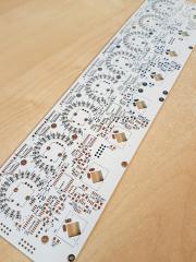
From the album: Hawkeyes MB stuff
Andy's newest - just a proof of concept at the moment - but with such a board, we hope to be able to realize a standardized MBNG user interface (aka ProgrammA) at some point in time. -
@pat_00 could you try to reupload these pictures? The forum disallows attachments larger than a certain size (i think it is 1MB?), that's probably why the images come up as broken right now - so you might either need to reduce the JPG quality (not necessarily the resolution) in your image editor before reuploading here or you could upload them as they were on another service (e.g. imgur, dropbox, ...) Thanks and many greets! Peter
-
@gotkovsky fantastic job, extremely well done, if it was one of your first DIY projects! Congratulations on your new sequencer and enjoy the upcoming weekend! :) Many greets, Peter
-
@gotkovsky Yes, you can run it from a good 5V/1A USB supply. I have a USB Power meter (just as @Smithy posted), and the v4+ current use hovers around 0.5-0.6A during normal use. On a sidenote, make sure you have a good power supply, if you experience reboots or dropouts, exchange it for another one - i tried to attach one SEQ v4+ and two LoopAs (all have about the same current draw) to a nominally 5V/3A rated PSU on a powered USB hub and experienced reboots - using the power meter i measured it all up and and the 5V rail dropped to 4.5V :) - another lesson learned, do not assume the PSU power capabilities label on the backside is correct - my cheap PSU could not even reliably supply 1.5A as indicated by the power meter :). Many greets, Peter
-
@gotkovsky thanks and that sounds good, enjoy your build!
-
@gotkovsky please also read my recommendation above. Another test you could do is pull the waveshare daughterboard off, switch its "powered-by" jumper from 5V in to USB mode and connect it without the wCore to your MAC using a mini USB cable. If that works (which is likely), then the problem is on the wCore somewhere, we'd need said hi-res pics, then. Good luck! Peter
-
@niles welcome to MIDIbox! :) For the Core kit, you will need pieces of 10cm, 20cm, 30cm and 40cm of 10-pin ribbon wire. (Core to MIDI8, LineTX, I2C and USB) For the Core kit, you will need 40cm of 16-pin ribbon wire (Core to SD Card) For the UI kit, you will need 7.5cm, 10cm and 2x20cm of 10-pin ribbon wire (SRIO bus through LeMECs, JA and LineTX) For the UI kit, you will need 25cm and 30cm of 16-pin ribbon wire (2x OLED Displays) And you need a 35cm split 16/8 pin ribbon wire (requiring 24 pins) to connect the new Activity Matrix displays (on JA) to LeMEC R. @gotkovsky - the waveshare board should be pushed onto the wCore PCB headers, so that the distance of the wCore underside is not more than 20mm (it needs to be installed on 20mm hex spacers in the case). If you don't manage to see the MIDI ports in MacOS, could you send us high-res photos of front and backside of the wCore PCB, so that we could have a look? As i saw, Andy was a bit quicker answering, he is younger and faster, hehe! Have a great weekend y'all! :) Many greets, Peter
-
@pat_00 if you don't have access to a hot air rework station (which would be the recommended way to do it), you could try to clip off pin by pin with very fine pincers and then desolder/drag away the pin remains with your soldering iron. This obviously destroys the ICs, but should not be too stressful for the PCB. But as Andy wrote, hot air desoldering should minimize the risk to lift any pads - after warming up the target area, the IC should fall right off :). Many greets and good luck! Peter
-
Hi and welcome to MIDIbox! :) I'd say there is a 50:50 chance, that they are original and will work. That ebay seller in german ebay seems to generally have quite positive feedback, but there are also some "fake component" comments. How it could work from their side is that they pulled/desoldered the chips from old hardware, i.e. old sound cards. That's also what i would recommend, e.g. get an old soundblaster with the OPL chipset from ebay for cheap and desolder with a heat gun - that way you can be quite sure it is an original! Most of all: have fun! Many greets, Peter
-
@Antichambre, probably the definitive version - it is nothing dramatic and should be quite easy to handle, as it will be quite modular (lots of small panels). Many greets! Peter
-
Andy is back from the states and has access to proper soldering and test equipment again :) Speaking for myself, we have finalized the move to the new house, thus i have more time. The v4+ modular extension is super high on our list, we are working on it: validation phase next and we need to design the eurorack frontpanels :). Many greets, Peter
-
@southpole you are welcome! Maybe not exactly the same, but you could also look into the native patterns of the MIDIbox SEQ - switching them on the pattern screen gives you direct access to different notes/melody lines on a group of four tracks, so you could also replicate the 16 x 16 step parts by switching through patterns, i think. Many greets and enjoy the weekend! Peter
-
@southpole maybe helpful regarding your first question - have a look at "Fx Loop" in the handbook: Fx Loop Is this an "effect" or a "tool" which is useful while editing long sequences... decide by yourself: Global Loop Mode: following modes are supported: All Tracks/Step View: loops all tracks around the visible step view All Tracks/Static View: loops all tracks around the selected Offset/Step range Selected Track/Step View: loops the selected track around the visible step view Selected Track/Static View: loops the selected track around the selected Offset/Step range Loop: enables/disables the Loop function. Can alternatively be switched via MENU+SCRUB buttons. Many greets, Peter
-
Great job, Bruno, Elektruck and southpole! Sorry for my absence, we were moving and I still have to unpack a lot of boxes until normal operations can proceed :). Because there was a discussion ongoing regarding resistors for color mixing and lowering the resistor values e.g. for custom keycaps with smaller windows - the superflux LEDs should be able to withstand more current, and in my experimentation i went as low as 10R for blue and green (use a higher value for red!) - but then the currents are way out of datasheet specs - you are on your own, then! :-) Imho it would be best to play safe and go for 47R, then these LEDs should have a very high life expectancy and the superflux brightness is then also somewhat balanced with the brightness of the OLEDs and the matrix displays. To achieve the red/cyan mix as seen in the first tutorial video, you can use a single resistor going from A to 1 (red color for the running step indication) and another single resistor going from B to 2 AND 3 (cyan color for the "step has a note" indication). That second resistor results in a blue-ish cyan, as the forward voltages of blue and green are slightly different, green will not be as bright as blue. You could also try with three resistors (there is a second hole in modern LeMEC boards or you could just attach to the same pin) for fine-tuned color mixing. Have a good evening! Many greets, Peter
-
@mcmurray just a heads up, parcel tracking says batch #2 of the cases should be delivered tomorrow or on tuesday, will make them available in the shop, once they arrive. As a new shop feature, you can now subscribe to "back in stock email push notifications", when you are logged in and are browsing the product detail page, e.g. of the case you want. Then you get an email instantly from the shop, when they are available. There probably is more demand than supply for this second batch of cases again, but we've asked Adrian to make batch #3 a bit bigger. If you don't manage to get a case from batch #2, the next batch should be inbound again in another few weeks. We'll get there and finally stabilize supply. Many greets, Peter
-
@synaptech well done - congrats also from my side, you have deserved a cold one! :) Enjoy your new sequencer! Many greets, Peter