
jjonas
-
Posts
422 -
Joined
-
Last visited
-
Days Won
24
Content Type
Profiles
Forums
Blogs
Gallery
Everything posted by jjonas
-
Hi, thanks for the reply, I realise now that it was all there, but I just couldn't see it! :-)
-
Hi, I was working on a multi patch with two separate instruments (bass and lead played by MBSEQ4) when I noticed that tweaking the filter depth (D.P) LFO for one instrument made the other one's sound filtered too. I don't know if it is a solution, but anyway reading the manual I figured that I should try assigning each instrument to a fixed oscillator in the CFG menu. The manual says for the CFG menu: O1..O6: selects an individual oscillator for the instrument. Take note, that this option also locks the oscillator for instruments which haven't explicitely assigned it. However, no such entry is visible either in the screenshot in the manual (just above the quoted text), nor in my MB6582's screen (version 2.043). Is the error in the manual or in the firmware? Concerning multi-instrument multi patch and filtering, what is the recommended way to do it? I'm not completely sure what the limitations of the SID hardware are. I understand that the chip has one filter which the three oscillators share. Let's say Ins1-3 are playing on one SID. If I want to filter one of them and leave two unfiltered, that's ok, but if I want two of them filtered, I can do that, but they have to use the same filter and thus same settings..? Anyway, I have the LR-channels centered on my mixer, and I was able to make the two instruments (Ins1 and Ins2) so that Ins1 is filtered and Ins2 isn't by switching the filter on for channel 1 and off for 2 and 3. When I switch off the "poly" setting in the CFG menu, an instrument seems to get assigned to whatever oscillator is was playing on when the "poly" setting was switched off, and this also determined which filter channel will affect it. It would be nice to have more control over this, and maybe the missing O1..O6 setting would help in this..?
-
Hi, I have two minor suggestions for improving usability (IMHO). 1. When saving a pattern, the interface is SMS-like. Say you want to give your pattern the category name "Lead". If you want to write "Lead" in an SMS on your cell phone, you press for "L", and then you can immediately start pressing another button to get to "e". With SEQ4, however, you have to wait until a threshold time runs out before you can start pressing for "e". If you don't wait, the "L" that you pressed in previously, will turn to "E". This is just a matter of convenience, and a case can be made for why the present system is good. Personally I think it would be better if SEQ4 save naming was in line with SMS'ing, because probably people – most people anyway :-) – write more SMS's than save names on SEQ4, so I'd argue that is the more intuitive way. 2. If one is using Wilba's front panel PCB, you have perhaps 50% of the top menu level entries available directly with the press of one button or MENU+button combo. But the top menu does include stuff that you want access to but cannot reach with buttons, so to get to what you want, you need to skim through lots of redundant entries (Edit, Pattern, Mixer etc.; redundant because you can access them faster with buttons). Would it be possible to have a file in the root directory of the SD card which is read once at boot, which would list all the top menu entries, and you could comment out the ones that you don't need, because you never access some functions through the top menu, but use buttons instead? That way when you hit the top level menu, you could always see 100% business? Perhaps there's better solutions, this is just the one that occurred to me first. But it could also be no-one else feels this is a problem that needs a "solution". What do people think?
-
Thanks!
-
Hi, I couldn't find MBSEQv4 drum track drum names for the 16 different drums in the MBSEQv4 manual, and I'm not able to figure them all out on my own. Perhaps they're standard drum machine stuff, but I'm not too familiar with those, so I need some help. It would make assigning drums to different slots easier if I knew what each abbreviation means, so if someone can help me out with this, it's much appreciated! Here are my guesses, please also correct me if I've got some of them wrong! BD = bass drum SD = snare drum CH = closed hat PH = ? OH = open hat MA = ? CP = clap CY = cymbal LT = low tom MT = mid tom HT = high tom RS = ? CB = ?
-
Hi, thanks for your reply! I have three chained AOUT_LC boards, two first for cutoff & resonance (channels 1-4, they're working), and third for VCA (5-6). (Channels are set in setup_*.asm.) So far I haven't stuffed the VCA board with chips, I've just checked the CVs first. So far I haven't been able to change the CVs on the third board from the control surface. (I have enabled V2A in the ensemble menu for the core in question). But at this point my question is about this section in the setup_*.asm file: ;; only relevant if one or more AOUT_LC modules are used: ;; define the resolution configuration here ;; 0: first channel 12bit, second channel 4bit ;; 1: first channel 8bit, second channel 8bit ;; 2: combines M1,M2 and/or M3/M4: first channel 12bit, second channel 12bit, third channel 8bit, fourth channel ignored! ;; all other values invalid! #define AOUT_LC_RESOLUTION_OPTION_M1 0 #define AOUT_LC_RESOLUTION_OPTION_M2 0 #define AOUT_LC_RESOLUTION_OPTION_M3 1 #define AOUT_LC_RESOLUTION_OPTION_M4 0 I'm not sure what 'Mx' refers to here, but I take it M1-M4 refer to the four AOUT_LC boards that can be chained. The first two boards (for cutoff/reso) are set with jumpers to 12bit/4bit, so the setting is here the same. However for VCA it seems better to make both channels the same, so I've set the jumpers for 8bit/8bit, and figured that I should set the setup_*.asm accordingly. Is this correct? BTW the AOUT_LC module info page says (bottom of page) that With two chained MBHP_AOUT_LC modules, you can control CutOff and Resonance of the right channel SID the same way. With V2A, volume can be handled a similar way (4 chained AOUT_LC modules required for this case). Is this correct, i.e. that you need two boards for VCA? Or have I misunderstood something?
-
Hi, I'm back on this topic since now I'm ready to start practical VCA tests with the MBSIDv2. However there are a few things I'd like to know before I start experimenting, just to make sure, and would like to ask people's opinion. (Here's the SSM2164 datasheet for reference.) 1. Am I looking only for attenuation? 2. According to the datasheet, maximum supply voltage is +-18VDC (p. 3); in my setup it's +-12VDC. Control voltage range is given as V+ and V- (p. 3), am I right to think this means that in a setup that's only for attenuation, the CV range is from 0 to 12VDC? 3. According to the datasheet, "Notice that a capacitor is connected from the control input to ground. Because the control port is connected directly to the gain core transistors, any noise on the VC pin will increase the output noise of the VCA. Filtering the control voltage ensures that a minimal amount of noise is introduced into the VCA, allowing its full performance to be realized. In general, the largest possible capacitor value should be used to set the filter at a low cutoff frequency. The main exception to this is in dynamic processing applications, where faster attack or decay times may be needed." (p. 8, emphasis added.) I have used 1uF caps, like in the example configuration on p. 8. It sounds like the MBSID VCA case would be one where relatively "faster attack or decay times may be needed", but I don't really know whether 1uF is "too big" for this purpose or not. Maybe it can only be found out with experimenting, but if anyone has opinions on this, I'd be interested.
-
I've always used a desoldering pump for removing solder, one like these: http://www.amazon.com/s?ie=UTF8&page=1&rh=i%3Aaps%2Ck%3Adesoldering%20pump
-
I tested this now only briefly, but I liked the changed (=faster) encoder behaviour, I think it's better than the old. I felt that even with the faster setting I could still turn the knobs slowly enough to have e.g. cutoff change slowly; I didn't feel like I have to use Shift+turn function to make it slower. I can see why that might be desirable, but personally, if the option was available, I'm not sure I'd make use of it. Just my 2pF...
-
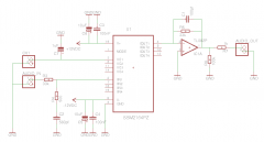
Hi, thanks for replies! I haven't tried yet whether AOUT_LCs trimmers are enough to do the trick, but I'll do that before I finalise my VCA PCB, and include a voltage divider if necessary. Based on sneakthief's reply I made a second draft of the schematic, with an additional diode in case of a "catastrophic mode", also and for reverse voltage protection. I'm not sure but I think 1N4148s will do for reverse voltage protection, their VR is max 75V and continuous forward current 200mA, aren't these the relevant numbers..? Plus I hope I put the polarity protection diodes the right way in the schematic :-) -12VDC line name (at the bottom) looks confusingly like it's positive, but in fact it's just smashed (previously it wasn't).
-
From the album: miscellaneous
-
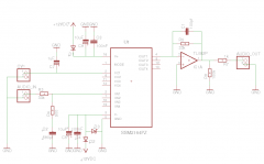
Actually the text "power supply and biasing circuitry" appears to refer circuitry inside the chip and not outside – I was too hasty with the datasheet, in fact it seems to offer a good application schematic (page 8). I drew the following schematic (below) for one channel, do you think it's ok? Mostly it's the datasheet schematic, but I combined it with a few caps from the other schematic (pdf) that I referred to, and didn't include a trimmer for adjusting CV as the setup I'm planning includes an AOUT_LC board, and the CV is set with the trimmers there. I left MODE pin open because it was open on "the other schematic (pdf)"; according to the datasheet leaving it open means a choice in favour of "Class AB" and against "Class A", which in turn means "Class AB operation refers to running a VCA with less current in the gain core, resulting in lower noise but higher distortion. More current in the core corresponds to Class A performance with its lower THD [total harmonic distorition] but higher noise.Class AB operation refers to running a VCA with less current in the gain core, resulting in lower noise but higher distortion. More current in the core corresponds to Class A performance with its lower THD but higher noise." I don't really know what this means in practice, do you think there's an obvious choice? One could always build an option into the circuit, so that MODE pin can be connected through a 7,5k resistor to +12VDC with a jumper. Or I just try it out when breadboarding the circuit. But I'm still interested in any opinions on this!
-
From the album: miscellaneous
-
I did take a look at the datasheet, but the shematic there was not explicit enough for me: it puts the text "power supply and biasing circuitry" where I'd need the circuitry to be :-) So that's why I tried looking for a schematic that had everything in it, without as much assumed knowledge as in the datasheet schematic. I'll try to draw a schematic this week based on the one I posted, the picture you drew and the SSM2164 datasheet, and post it here for you and others to evaluate, is that ok..?
-
Thanks for your reply! The MFOS is good for having a schematic and PCB layout available (I'll draw my own PCB in Eagle), though the SSM2164 would be more footprint-effective with four VCAs in one chip. Do you have a schematic for the solution you are using? At the moment this schematic (pdf) for a SSM2164 VCA looks like one I can read, any opinions? For each channel's CV it mixes two CV inputs (1A+1B = CV1), I guess the other branch (say B) can be left out, plus the four TL082s can be replaced with two TL084s..? A few more questions. I found out while googling that seppoman had designed an SSM2164 VCA as well, though he never got around to posting the schematic or PCB here. Anyway, that with an external VCA "you just set the oscillators to A=0 D=0 S=15 R=0 and control volume through the SID engine's envelope" to which TK adds that one must activate the GSA flag in the OSC menu as well. Does this mean that with external VCAs one has to manually change ADR=0 and S=15 with every patch, separately? I.e. the SID envelope is not overridden by ensemble setting V2A, the envelope information just gets sent to AOUT in addition?
-
Hi, now that I've gotten external filters and AOUT_LC working, I was thinking of trying my luck with external VCAs "to overcome the infamous ADSR bug of the SID" :-) I was wondering whether anyone else uses external VCAs, and if so, which one? I'd be looking for relatively simple DIY. Web search produces several options, but I'm not sure which ones would be suitable as there's often a lot of tech speak I don't understand for sure. If someone is using a particular DIY VCA for which there is a schematic on the net, I'd be interested. Otherwise, what do you think of e.g. the following options: http://yusynth.net/Modular/EN/VCA/index.html ("Simple VCA") http://hem.bredband.net/bersyn/VCA/vca_shootout.htm (several) http://www.sdiy.org/philgallo/mgbvca.html (SSM2164 Based Voltage Controlled Amplifier)
-
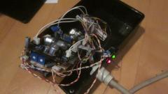
Hi, I decided to give up on AOUT_NG because I've already fried two chips (maybe three, I'm not sure, and not keen on testing whether it really is broken), tried two separate AOUT_NG builds without getting it working on the long run, and I think at some point I blew the CORE4 PICs J6 as well – the PIC seems to be operating normally otherwise, only the J6 doesn't seem to send out any information. So inspired by Imp's posts in this thread I tried out two AOUT_LCs, as I figured I'd much rather fry 595s in a socket than TLVs surface mounted on a PC :-) I hadn't really considered the option before, as there was much more info around for calibrating SSM2044 with an AOUT_NG than with other options. So, I changed a few lines in the setup*.asm, recompiled etc. It works. At first it seemed it didn't work either, but then I tried it on CORE3, where it did work. So it was here that I noticed that the CORE_J6 was not working, and I reckoned it was because of my AOUT_NG tests. The SSM2044 board's problem was that for some reason the LM13700's other side was not working, which was fixed by switching in another one. Here it is, the external filter box gets all it needs via the extension port. The red LED & switch are for +/-12VDC on/off, and the green one for whether the filter is set to on or bypass (via J5 digital switch pin). Thanks for all who helped with troubleshooting!
-
From the album: jjonas - midibox SID
I salvaged the box from my workplace's junk pile. Miraculously it's just big enough to house two AOUT_LC + filter PCB stacks really snugly. -
From the album: jjonas - midibox SID
SSM2044 (seppoman) filter PCB stacked with two AOUT_LCs. Switch & red LED for switching bipolar 12VDC on/off, green LED for indicating whether the filter is switched to on or bypass (LED connected to CORE4_J5 digital switch pin). -
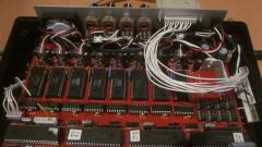
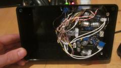
From the album: jjonas - midibox SID
This pic shows the wiring inside the MB6582 for an external filter box, attached to the main unit with the extension port. The wires provide: 1) +12VDC 2) -12VDC 3) CORE4_J6 (5 pins, including +5 & GND) 4) CORE4_J5 (1 pin for digital switch) 5) Left & right audio send (from CORE4 SIDS) 6) Left & right audio return -
Ok, I'm now testing a new AOUT_NG board with MB6582. I thought I'll do it in stages, as previously everything seemed to be operating ok for an hour or so. So now I've connected the AOUT_NG only to J6_CORE4 – the AOUT_NG led is on, chip not getting hot. I thought I'll leave it like that for a few hours, then add +12/-12 and see what happens. I tried Imp's test setup to test the SSM2044 board on its own yesterday. The test setup seemed to be working ok, though not the board's second resonance channel :-) I'll have to spend some more quality time with it. Does it btw matter – for non-audio technical reasons – if the PSU I'm using is the Meanwell RPT-60, i.e. a switching PSU..? It's the same I'm using for the MB6582, so it would be most convenient to use that for the AOUT_NG and filter board as well.
-
That's great news! Concerning stereo samples, do the other limitations still apply, i.e. it still has to be "44.1kHz 16 bit RAW signed little endian", even though it can now be either monophonic or stereophonic..?
-
The schematic does tell you how to connect the LEDs, though not necessarily what the best way is to place them on your control surface. Here's how I did the modulation matrix LEDs, which may or may not suit your purposes. I attached the LEDs directly onto the front panel (the holes are snug enough to hold them all in place), and then soldered the necessary anodes/cathodes together with pieces of wire. I understood you are going to solder them onto a veroboard first, so you might have to modify my approach a bit. Before you start placing the LEDs on the board, might want to cut one of the legs of each a bit shorter than the other – cathode or anode, doesn't matter as long as you know which one – unless they already are; that way you will know which one is which. That makes soldering them matrix-style easier as well, as there's two "levels", where the first has the anodes together vertically, and another where the cathodes are together horizontally (like in the picture above; I'm not sure how well this 3D property can be seen there). If you're going to use veroboard which has "dots" on the solder side, you probably want to solder both legs on the solder side; in my experience the "dots" on this kind of veroboard come off quite easily if you heat them too much, or if you apply too much pressure – both can happen easily, at least to me :-) Personally I wouldn't use "dots" veroboard for anything. If you're using "striped" veroboard (where the solder side is much stronger), you could separate the anodes and cathodes by soldering e.g. the cathodes on the solder side, and bending the anode legs to that they stay on the "top" side of the veroboard, and connect the necessary anodes with wires. But this is in case there will be enough room left for the legs to be on the top side, between the veroboard top and control surface front panel. I just hope this is no too difficult to visualise :-) Bridges means just wires. The normal way to upload applications via the MIDI connectors is to use a USB-MIDI interface and MIOS Studio. There's a blacklist on the wiki, which lists the interfaces that people have had problems with. The list is by no means complete. I bought the one I'm using on eBay for a few euros, and luckily it worked. Here's an example of what I mean. I don't know whether this particular model will work – it might, or it might not. I don't know how many of the various USB-MIDI interfaces don't work, maybe it's just a few and the rest are ok or something. Using a USB-MIDI interface to upload applications on the PIC presupposes that the MIOS bootloader has been flashed on the chip.
-
Hi, re testing the filter PCB with an external PSU setup, I don't have a functioning AOUT_NG at the moment, so I can't check this, and that's why I'll ask: which voltages do I need to "emulate" AOUT_NG control voltages, both unipolar and bipolar? If I recall correctly, unipolar range is 0–10,67 VDC, and seems easy enough to emulate with a single pot, but what about bipolar? Somehow unipolar control voltage seems more intuitive to understand, but I don't really get how a bipolar CV works, and so I can't really improvise a test setup involving it on my own. Further: on the wiki page for SSM2044 PCB it says: "If you want to use this module [seppoman SSM2044 PCB] together with “non-AOUT†CV sources, you will need to add the control summer circuit externally." (Description of the "control summer" is in the 'Design' section of the entry.) Are there consequences from this to a test setup?
-
Altitude: Thanks for checking, that's an artifact that's visible also on Eagle at this level of zoom. I ran only DRC, it produced a few errors like this, all of which but one are visible here. Do you they matter..? I kind of thought they don't, but I might be wrong. If they do matter, is it clear to you how they would matter in this case..? Imp: Sorry I don't understand your question: "Did you solder the parts that connect to wires on top and bottom layer (e.g. left leg of R16) on both sides?" Your idea for testing SSM2044 board separately like that is definetely something I'll try!