

jjonas
-
Posts
422 -
Joined
-
Last visited
-
Days Won
24
Content Type
Profiles
Forums
Blogs
Gallery
Everything posted by jjonas
-
I'm not 100% sure if this is what you're after, but you have to use a Loopback track to control the track with the Chord parameter layer to get all the chords in a key (e.g. C, Dm, Em, F, G, Am Hdim), instead of chords with the same root note. Personally I find polyphonic note recording into multiple note layers easier than using a chord layer + loopback, because it can be done with just one track and I don't remember which letter stood for which chord. Chord layers might be useful if the number of available note layers is limited, though. Also, note that even if you choose Track Type 'Note' or 'Chord' and then initialize the track, you can always change the individual layers to whatever you like. I guess the only fundametal difference is between Drum and the other track types; consider 'Note', 'CC' and 'Chord' track types as just convenient presets, which you can change. So if you have chosen Track Type 'Note', you can change any of the parameter layers into a chord layer on the Event page, where on the right LCD you can choose Parameter Layer (<i>Layer</i>, GP knob 9) and what that layer does (<i>controls</i>, GP knob 10).
-
Thanks for the tip! I just did the same, but I used soft wire and double sided tape to fasten the adapter to the PCB.
-
Hi, I noticed that if a loopback track is controlling another track with the latter in Transpose mode, the controlled track will take its Transpose-controlling note from the last note layer of the controlling track – the last one that has a note value in it, that is. Offhand I think it would be handier to take it from the first note layer, because the first note layer's contents are most of the time easily accessible by pressing a single button, but for the other note layers the you have to enter Layer View (EDIT + GP button). This came up when I was fiddling around with loopback tracks and and switching between Transpose and Arpeggiator modes. I forgot some chords in a track that was controlling the transpose of another track and was confused why changing the value of the first note layer has no effect on the transpose. EDIT: I'm on 4.089
-
Hi, I noticed that live recording works a bit weird if recording is started with Jam page AStart=on. <Live> recording works ok if you have Jam page Rec=on, the sequencer already running and you're in Edit view. But if you set AStart=on and try to start recording either from the Jam page or from the Edit page (with the sequencer stopped, and started automatically only when you hit the first key), there's problems, and it seems <Step> recording setting 'Step' is involved. However, <Live> recording doesn't have the 'Step' option available (only Mode, AStart and Quantize), implying that it should have no effect for <Live> recording. Given this, it would feel natural to expect automatic recording (AStart=on) to start from step 1, and it seems that this is indeed what the sequencer tries to do. But if the <Step> recording setting 'Step' is set to 5, if I have <Live> recording selected and if AStart=on, and I then hit C-E-G, one of the notes gets recorded in step 5 and the other two notes in step one. Even if <Step> recording 'Step' is set to 1 and I hit C-E-G, one of the notes doesn't get recorded anywhere, and only two of them get recorded in step 1. The problem is there also in <Live> recording Mono Mode: If <Step> recording 'Step' is set to 9, and AStart=on, the first (mono) note is recorded in step 9, even though the sequencer does start from step 1, and all the subsequent (mono) notes will be recorded properly. EDIT: I'm using 4.089
-
Sorry I forgot to mention that, I'm using 4.089 (on an STM32F4, in case that's relevant).
-
Hi, what is the expected behaviour in Song Mode when I've got two patterns, each has the same three tracks of different lengths (8, 16, and 32 steps), with only the notes changing so that I can tell a pattern has changed;Guide Track is disabled (set to ---);Measure (in Options) is set to 16;Pattern Change Synchronization is set to 16, but disabled;none of the tracks is synced to Measure?Given these setting, should the Measure setting in Options affect the behaviour? If you set Measure to 16 and hit PLAY, things work like this: Song Pos.A1 (play 1:A1 x1): G1T1 (16 steps long): Plays once;G1T2 (8 steps): Plays twice;G1T3 (32 steps): Plays the first half.Switch to Song Pos.A2 (play 1:A2 x1): G1T1 (16 steps): Plays once;G1T2 (8 steps): Plays twice;G1T3 (32 steps): Plays the second half.This is how it will loop if you don't stop the sequencer, and it's logical enough. The question is however: what triggers the change to the next Song Position (or the next loop within the same Song Position)? In the above example Measure was set to 16. If you set it to anything below 16, no Song Position changes will trigger, instead the current Song Position will loop forever, and it's very much like in Phrase Mode (where Measure doesn't affect pattern length unless "sync to measure" is set to "yes"). If you set Measure to 32, the following will happen: Song Pos.A1 (play 1:A1 x1) G1T1 (16 steps): Plays once;G1T2 (8 steps): Plays twice;G1T3 (32 steps): Plays the first half.Switch to Song Pos.A2 (play 1:A2 x1): G1T1 (16 steps): Plays twice;G1T2 (8 steps): Plays four times;G1T3 (32 steps): Plays the second half, then loops to beginning and plays the first half.Loop back to Song Pos.A1 (play 1:A1 x1) G1T1 (16 steps): Plays twice;G1T2 (8 steps): Plays four times;G1T3 (32 steps): Plays the second half, then loops to beginning and plays the first half.Switch to Song Pos.A2 (play 1:A2 x1): G1T1 (16 steps): Plays twice;G1T2 (8 steps): Plays four times;G1T3 (32 steps): Plays the second half, then loops to beginning and plays the first half.From here on the sequence stays the same. If you set Measure to 64, the first Song Position is still only 16 steps long, just like with Measure set to 32, while the rest behaves more predictably (but is kind of "out of sync" the same way as with Measure set to 32). The question is: why is the first Song Position played differently the first time, and only the first time? You can kind of fix this by changing Pattern Change Synchronization (PCS, Option 2/14) from 16 to 32, but it feels counter-intuitive that even with PCS set to 16, only the first Song Position is affected. PCS disabled/enabled (Option 3/14) seems to have no effect on how the Song Positions are sequenced.
-
With the buttons it might be a debounce problem, if "jumping values" means one press changes e.g. two steps instead of just one (and not going all over the place). I managed to fix it like in the thread below ('Button press delay'). It involves changing the source code and compiling it, but it wasn't hard even though I had no previous experience. Could be that the encoder has a similar problem too. I don't know whether there's a parameter in the source code for that as well, but an alternative nuts-and-bolts option is just to try another encoder. Re the chip turning off, I can't help you there, but I think it's normal that SID chips sound slightly different even if they're from the same series.
-

Problem with encoders after migrating from LPC17 to STM32F4
jjonas replied to jjonas's topic in MIDIbox SEQ
Hi, if I don't have the displays connected, how can I tell how the encoders behave? Anyway, I disconnected J19 but left the displays, SD card and J8/9. Now the problematic encoders are working, including data wheel. Apparently all encoders and buttons are now working, so I think I was under the false impression that the panel PCB connector J2 must be connected to J19. What is the purpose of the J2 connector on the panel PCB? Wilba's construction page mentions only it's connected "to additional control elements in the Chain". I don't know what that means. According to the STM32F4 schematic, J19 is "for AOUT and similar 5V based SPI Devices", and actually now that I checked, the LPC17–MBSEQ4 connection guide shows that J19 is used for AOUT. I don't remember anymore why I connected LPC17 connector J19 to panel connector J2, I must have thought it's necessary (perhaps I was thinking one is DIN and the other is DOUT). At any rate it didn't cause any problems. Anyway, based on quick testing, everything seems to be working now with J2–J19 disconnected. Thanks! -
Hi, I decided to migrate from the LPC17 based core to the STM32F4 based one. After doing that I noticed that encoders 13-16 and the data wheel work now only in one direction, and move several steps each time. All other encoders and buttons seem to work ok as far as I can tell. I'm using the Wilba front panel and the settings file for it. The LPC17 based core has worked ok with the same front panel. What I have connected to the core (both new and old) is the SD card (J16), the displays (J15A + J15B) and J8/9 + J19. Both cores are running the firmware v4.089 and identical hw setup files (the default ones for Wilba front panel from the firmware zip on ucapps). Both cores are running on USB power. If I switch the front panel between the old core and the new one (SD card connected to J16 in both cases), the old one always works normally, but the new one has the problem I described above. (As an extra quirk, with the new core, in addition to the problem described above: the encoders 9-12 are also really fidgety if the panel is on my computer desk, but if I have the panel on the floor or if I hold it in my hand, there's no such problem. When the panel is on the desk with the encoders fidgeting, it doesn't matter whether I touch it or not. The STM32F4 core location doesn't seem to matter. With the old core it doesn't matter where the panel or core is located, all works ok. But I'm not really after a solution for this, thought just that I'd mention it.) I tried using the default hardware configuration file from newest firmware package (instead of my old own one which has a few customisations), but it didn't make a difference. I tried changing the hw setting file's encoder DETENTEDx setting but none of the setting were helping, all settings 1-5 produced completely unusable results (sometimes the turn of one encoder triggered change in a neighbouring step as well!) I couldn't get back the normal behaviour I had with the old core, and still have, if I just switch the ribbon cable connectors to the old core (DETENTED3 works there). The misbehaving encoders are attached to shift registers 5 (GP encoders) and 6 (data wheel) on the panel, I wonder if this has anything to do with it. Probably not, I doubt there's anything wrong with the panel as it works flawlessly with the LPC17 core. I scanned the STM32F4 for soldering mistakes but couldn't find any. I replaced the 74HCT541 on the STM32F4 to see if that was the cause of miscommunication – after all that's the IC that's communicating with J8/9 and J19 – but it didn't make any difference. I'm not sure where else to look.
-
From the album: miscellaneous
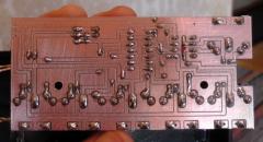
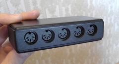
Drawn with Eagle, converted to g-code with pcb-gcode (an Eagle ULP) and routed with a small CNC machine. -
From the album: miscellaneous
-
From the album: miscellaneous
-

From the album: miscellaneous
-
From the album: miscellaneous
-
From the album: miscellaneous
-
Yes, my mistake, I meant pin 6.
-
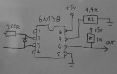
Hi and thanks, the links you provide are a bit more "fundamental" than what I had in mind, dealing with atom level operation (electrons and holes) of semiconductors, while I was looking for a more "mundane" explanation. Sorry if my original mail wasn't clear enough. I know the basic operation of an NPN transistor (hfe, B-E threshold voltage etc.), more or less, but it's a bit shaky and not comprehensive, so I was looking for an explanation more along the lines of the video below. The video was very useful to watch (also for how MIDI works in general), but it didn't really get into the details of the transistor operation at the end of it tutorial. I might be mistaken, but based on the video it seems that the second transistor (see schematic in the first post) functions just as a switch, switching between full saturation and whatever is the opposite of saturation :-) , i.e. on/off. The circuit that I have is the one below (sorry that the image is a bit dark), and my question is what function do the resistors R1 and R2 serve, and how would one go about determining the best values. (The MIDI specification gives a schematic only for PC-900 optocoupler and mentions that 6N138 or others can be used with modifications, but doesn't say what those modifications are.) I guess R2 can be found out using an oscilloscope, to see which size enables the shortest propagation delay (like explained in the video at this point). Is the function of R1 just to limit the current flowing through the second transistor to ground when it's fully saturated, i.e. when pins 5 and 6 have zero potential difference between them..? If so, is the maximum current to be found in the 6N138 datasheet alone, or should it be also considered, as per Kirchhoff's current law, what amount of current the receiving device can take..? On the receiving end there is a 220R resistor to limit the current when the transistor is off and won't let any current through, so I guess we don't have to worry about that..? But when the second transistor is fully saturated, it will practically suck up all the current, so one might think that the current limiter R1 size is in practice defined only by how much current the transistor can take. If so, the rating should be found on the absolute maximum ratings section of the datasheet. I'm not sure what it's called, but can someone confirm it's "Output current at 25°C = 60mA"? If that is the case, then R1 value should be 83R at the very least (5V/0.06A=83,33?). I've tried R1 values for circuit below at 440R, 1k, 4.4k and 10k, and they all appear to work.
-
From the album: miscellaneous
-
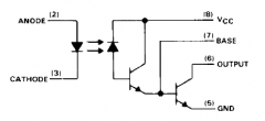
Hi, I would like to understand how the output side of a 6N138 works. Here is a 6N138 (datasheet): What happens when the input side LED flashes to "1", and what happens when it goes off for "0"..? Especially I'd be interested in a step by step walkthrough on how the transistors work when the first one in the series (a phototransistor, I take it) gets a signal from the LED. If we're taking the MBSIDv2 core schematic as a concrete reference with resistors, we have 5,6k at pin 7 going to ground, and pin 6 is connected to signal out and via a 1,2k resistor to ground. I understand that the 5,6k resistor enables the output transistor to operate faster, but what about the 1,2k at pin 7? There's different MIDI out schematics on the net with the value varying a lot (from 470R to 10k, even though the latter was on a 6N136 which might make a difference), so is it that the output current doesn't really matter (as long as it's not too big), what matters is only whether the voltage at pin 6 is high or low?
-
From the album: miscellaneous
-
Hi, some time ago I made an Arduino based custom control surface for DSI Tetra to control 95 or so parameters (via NRPN), inspired by the Waldorf Blofeld button-encoder matrix. I thought I'll drop the info here too. Here's a video of the basic operation: I also posted DIY instructions & the code on the DSI forum, here's the link in case anyone's interested. Stupid though that you have to register in order to read the forum. http://dsiforum.com/viewtopic.php?f=19&t=6778
-
Hi, I noticed that the state of Jam page option <i>Fwd</i> is not saved when you save a session, but it's always <i>on</i> when you open a session. (I'm using 4.088.) It's not a big deal, but the <i>Fwd on</i> setting interferes with the MIDI Router setup I have for my "base session" where I always start working. I need to turn the <i>Fwd</i> option off manually every time, and it would be nice if this wasn't necessary, but instead the state was saved. A few details on my setup: I have one MIDI controller keyboard and one (small) synthesizer keyboard . I select a channel on the controller and the router routes is everywhere (so it will play the synth that is listening to that channel), whereas the keyboard-synth is always on channel 1 (with local off), and the router routes the notes played on it to whatever is selected with the Group/Track buttons on the SEQ4. This way I can play whichever synth with both of the keyboards – including the keyboard-synth with the controller, if 37 keys are not enough for a two-hand-piano style playing, for example. However, if the Jam page <i>Fwd</i> option is on and I control the keyboard-synth (on ch.1) with the controller (on ch.1), the <i>Fwd</i> option will forward the notes I play on the controller (which are supposed to play only the keyboard-synth on ch.1) to the synth that is selected on the SEQv4 as well. This means I cannot control the keyboard-synth's synth engine with the controller AND at the same time use the keyboard-synth's keyboard to play some other synth. This is a relatively small thing and if changing this involves complications, it's probably not worth it, but it took a while to realise that the Jam page <i>Fwd</i> option has this effect, and that the fix is to switch it off manually at the beginning of every session.
-
There was a thread last year that dealt with some things concerning (MBSID) wavetables, where I tried to give a simple example of a wavetable function (see message #5 in the thread). It's not thorough by any means, but maybe it will get you started, and you can ask more specific questions later when you (hopefully) have a rudimentary idea of how the wavetables work. (See also the manual's section 'WaveTable Configuration menu'.)
-
If you can flash the MB6582 hex, you can flash the bootloader hex (and then upload the MB6582 app, and many other midibox apps, via midi). See here for more info: http://ucapps.de/mios_bootstrap.html You can download the bootloader (mios_v1_9h.zip) here: http://ucapps.de/mios_download.html As to the USB-MIDI interface, there's a non-exhaustive white list: http://www.midibox.org/dokuwiki/doku.php?id=midi_interface_whitelist ...and black list: http://www.midibox.org/dokuwiki/doku.php?id=midi_interface_blacklist
-
Where did you buy the PICs? Are they really blank, i.e. no bootloader?