

tob
-
Posts
19 -
Joined
-
Last visited
Content Type
Profiles
Forums
Blogs
Gallery
Posts posted by tob
-
-
Thanks for the tips!
-
I go to Berlin in November, can anyone recommend me a synth shop, museum or exhibition. Or something else fun?
-
If I have the midibox sid stereo setup (2 sid chips) can I play drum och the LEAD at the same time?
If so can I split the midikeyboard or Can I two midikeyboards?
-
I seen this interface on DE and on ebay
http://www.dealextreme.com/p/usb-to-midi-cable-with-16-midi-input-output-channels-1-8-meter-11277
Has anyone got it working?
-
I reversed the polarity on the core module directly to the J2 pins.
Where do I start to troubleshoot, what componets do you think are dead.
I had every IC in pic and Optocoupler and also a display.
What parts do you think is borken:
- resitors
- capacitors
- electrolytic capacitors
- PIC18F4685
- Optocoupler 6N138
- Diode
- TrimPot
- Crystal
- PCB?
- LCD
The volatge was correct but polarity wrong.
Now I got some strange chars on the display.
http://imageshack.us/clip/my-videos/534/hqg.mp4/
Where do I start?

-
Thanks for your help, now I know what was wrong. I had wrong polarity to J2
I putted the pic and opto in the sockets with wrong polarity! :cry:
I was fooled by the left + on the picture
http://mbhp.avishowtech.com/images/core/coreR4DETAILJ2.gif
and I missed +/- on my multimeter, when I checked on the points.
Very stupid!!
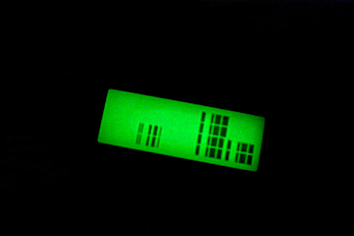
Now when I connect the power with right polarity the background light of the display is lighten up.
But the display is displayling some squares and then it disepears.
Do you think the core8 is bricked when I switched the polarity?
-
I desolder the bridge reflector and now I got +5 on every pins ( I didn't see any instruction to desolder BR1?)
When I put in the two IC and turn it on I now I get around 1.6V on the points, is this wrong?
-
Sounds like something is shorting the 5V rail, check for continuity between +5 and GND
It's the pcb and componets from smashtv.
I can't see anything with my eyes, is it possible to measure shortingin some way?
I have a multimeter with ohm,A F,V (DC & AC) and HZ plus a beeper.
My bridge reflector (BR1) get's very hot is this normal?
I get a beep when I put the probes on J2 but not on J1.
-
I have build this PSU from the c64 brick
http://www.ucapps.de/mbhp/mbhp_8xsid_c64_psu_optimized.pdf
I get +14VDC and +5V.
I have removed the 7805 regulator from core8 module and I have bridged leg 1 and 3.
But when I connect the +5VDC to the core module J2 (no others module connected and no display and no IC i sockets) it drops to about 1.7VDC on all measurement points.
IC1:MCLR(1) - IC1:Vss(12) = 1.7V
IC1:Vdd(11) - IC1:Vss(12) = 1.7V
IC1:Vdd(32) - IC1:Vss(31) = 1.7V
IC2(8) - IC2:(5) = 1.7V
What can be wrong?
-
Ok, I bought the 1 x core8,2 x sid+1 x DINX4. My first thoughts was to build the minimal control surface and then I changed and wanted to go with the large control and now I'm more into the MB-6582 control surface.
Maybe I go for the minimal anyway :frantics:
-
no, because the two output voltages of the C64 psu are added to about 14V and the 7809 / 78L09 on the sid module regulates this down again.
I missed that text on the connector 14VDC, I thought 7809 always delivered 9V. But now its 5+9V?
Thanks anyway...
-
I have a CORE8+2x SID modules can I use the MB-6582 control-surface?
-
I budling a core8 + sid module and LCD. I bouth everything from smashTV and going to use a C64 psu (brown).
In the instructions i read to bridge the 7805 on the CORE module:
http://www.ucapps.de/mbhp/mbhp_8xsid_c64_psu_optimized.pdf
But my SID-module also contains a voltage regulator, should this also be bridged?
-
I give it a try, when i done with my core+2xsid modules. :laugh:
-
-
Is it possible do this on the midibox SID?
-
Thanks I try it, are they any difference on these chips? (I can't find any information about it) I read here on the forum that the volume and sound can separate from different rev of the chip.
-
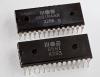
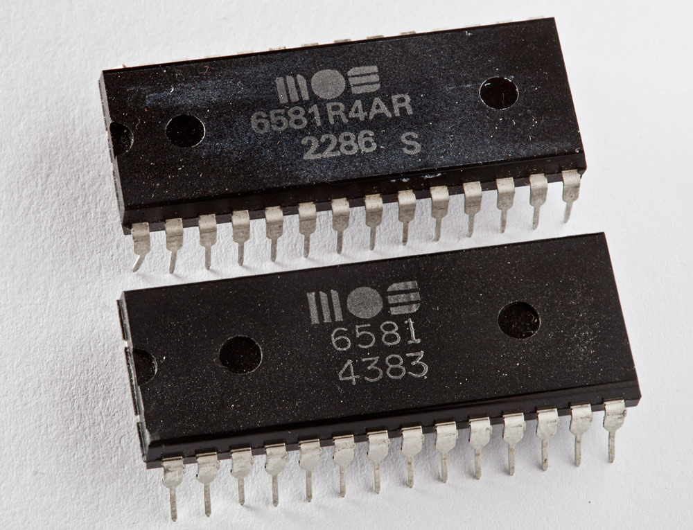
I got two SID-chip but will they be good in a Midibox SID stereo setup?
1x 6581R4AR 2286 s
1x 6581 4383
connect 8x8 led matrix with only 16 pins?
in MIDIbox SID
Posted
How can i connect this to the dout module?
http://www.ebay.com/itm/250910900835?ssPageName=STRK:MEWNX:IT&_trksid=p3984.m1439.l2649