

Tim B
-
Posts
11 -
Joined
-
Last visited
Content Type
Profiles
Forums
Blogs
Gallery
Posts posted by Tim B
-
-
Hi,
I have an older MBHP_CORE_V3 at home and I want to turn it into a midibox LC, I was wondering if this graphical LCD will work:
If not does anyone have a link to a graphical LCD which is known to be compatible?
Thanks!
Tim
-
Thanks for the replies guys!
Sorry I forgot to mention in the original post that it's a Pic 18F452, so I guess for that one I need all the 8 datalines right?
@Wilba: Wow, thanks for your generous offer! I live in the Netherlands. I see on the Australian post website that the cheapest way for sending regular post or a package is between $12-20,- which isn't too bad! I'll PM you right now!
-
Hi fellow midiboxers!
I have followed this guide from the UcApps website to build an lcd cable: http://www.midibox.org/users/jim_henry/building_a_midibox_lcd_cable.pdf . I have attached the datasheet of my LCD and the pin numbers exactly match those in the guide (if I'm correct).
I've soldered all the cables to the correct pins and I only got the blocks on screen. So then I've resoldered everything again after checking for broken cables with a multimeter and made sure there were no shorts after soldering.
- I've uploaded Mios 1.9G with MiosStudio and after that the Midibox 64 app, MiosStudio says Mios8 is running fine. The core began outputting loads of midi messages as expected since the Ain pins weren't grounded, after temporarily connecting 8 potmeters they worked as expected.
- I've tried the LCD on 2 different core8 modules (both with a different Pic) and both show only blocks
- The backlight lights up as expected, the contrast and brightness potmeters work as expected
Could the only reason be that datapins d0-7 are incorrectly connected? Or are there more possible causes for this behaviour?
Thanks in advance!
-
looks like there´s a short between +5V and GND somewhere...check and doublecheck all solderings... ;)
Thanks Nuke! I checked every pin and removed excessive from some points, and you were right. I checked again for shorts, none turned up and I finally got my 5 volts!
I'm so glad that it's not a broken part I had to track down or something, haha.
-
When I turn on my core module and try measuring the pins like described on the Ucapps website:
Check the voltage levels between the most important pins with a multimeter (analog or digital doesn't matter) before plugging the PIC and the 6N138 into the socket:IC1:MCLR(1) - IC1:Vss(12) = 5V
IC1:Vdd(11) - IC1:Vss(12) = 5V
IC1:Vdd(32) - IC1:Vss(31) = 5V
IC2(8) - IC2:(5) = 5V
it always displays 0 volts. But when measuring between the J1 pin and for example pin 1 of IC1 it does measure 9 volts that my psu is supplying.
Does anyone know what might be the cause of this?
Thanks!
-
do you have access to a connectivity tester? a multimeter (you need the resistance test) works too. if you connect one tip or clip to the middle tip inside the hole on the front you can measure by probing them with the other cable which of the solder lugs is connected to the tip (R=0 ohms or a beep/light)
one of the other lugs should connect to the outer metal sleeve. you can connect this one to the ground pin too so your metal chassis is grounded that way.
on the core it actually doesn't matter which orientation you choose as there's a rectifier behind the pins.
Thanks for the fast response Rosch! My father has a multimeter, so I think I'll pay him a visit today! :)
-
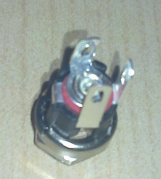
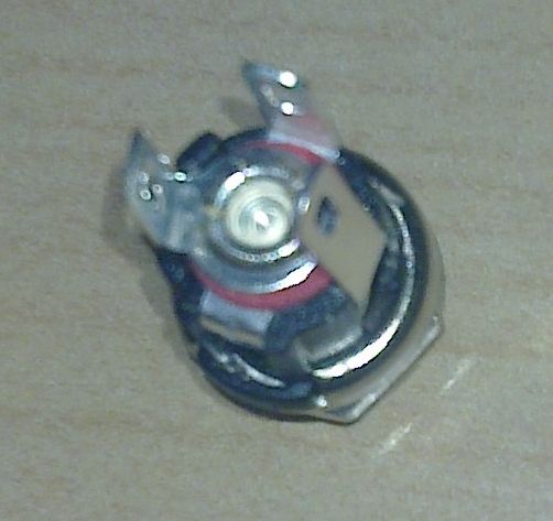
I've finished my midibox core with a kit from Mike's midi shop. Now I am wondering how to connect the power connector to the board.
I assume + and - go to the J1 connection on the core, but there is also a third pin on the power connector, I assume that is the ground pin, but where do I connect that one to?
Also could someone possibly tell me how I can identify the pins on the power connector (see attached pictures).
Thanks in advance!


-
... actually it's not one Channel but one port
The mapping thing (editing the Mackie/Logic protocol) also can be done with Sequoia/Samplitude. Now there it is also possible with your Cubase, I don't understand the problem from your first post anymore.
If you want to keep all the existing LC-Features/Controls while adding other controls, just take another Core and connect it to another port and map the controls you need.
Greets, Roger
Thanks Roger, yeah, it was a typo, I meant to say port instead of channel!
That's a good idea to use 2 cores! I think I will do that. I think I can use one core's midi out as midi thru then and patch it into the midi in of the other core so I can send all the data through 1 midi out.
-
Thanks for all the replies!
@TK: I know that the Mackie/Logic control protocol takes up 1 channel, but I have been using a Behringer BCR2000 with Cubase and mapped some controls as Mackie controls and others as normal midi. So at least with Cubase it's possible. Besides mackie control only uses CC# 16-23 the rest is all midi-notes and pitchbend.
So it's not possible? Or should I change some code in the LC program?
@findbuddha: I will seek out information about the core32 and the mf_V3 modules. The inputs available aren't going to be a problem. I only want to add the 8 encoders and about 50 buttons.
Thanks again!
-
Hi,
I'm considering building a midibox LC and I was wondering if the LC program allows for extra buttons, rotaries or encoders to be added to which you can assign your own midi messages (like a normal midibox 64e).
I saw something about a Generic Midi mode while reading through the program's code, but I guess that means that you have to switch to that mode on the machine by a key combination?
I would like to be able to simultaneously use LC controls and normal midi controls, is this possible? (if not I could always use something like MidiOx or Bome's midi translator)
Thanks!
Tim
Will this graphic LCD work?
in MIDIbox HUIs
Posted
Thanks for the reply Thorsten! I will search this forum some more to find working lcds! :)