

TK.
-
Posts
15,261 -
Joined
Content Type
Profiles
Forums
Blogs
Gallery
Everything posted by TK.
-

Seq 3.4 Glide not working on following note with same value...
TK. replied to nuke's topic in MIDIbox SEQ
I checked the source code: there is an explicit check if the note is equal to the previous note; in this case a Note Off event will be sent before the note will be played again, accordingly glide won't be activated. SEQ_CORE_Clk_SendEvent_NoOff ;; current note != old note: play off event later for a proper legato movlw SEQ_TRKVARSTATEx bsf PLUSW2, SEQ_TRKVARSTATE_LEGATO SEQ_CORE_Clk_SendEvent_NoLeg [/code] So, it seems that this is the intended behaviour - but I don't remember why. Probably because a user complaint about it ;) (Please don't ask for an option to alternate this behaviour - you know that MBSEQ V3 has passed it's lifecycle...) Best Regards, Thorsten. -
I took all Rob Hubbard songs as reference, since I know these tunes since centuries. ;) Best Regards, Thorsten.
-
No!!! ;) This issue could be related to the wire impedance. How many DOUT modules are connected together, and how long are the cables? Best Regards, Thorsten.
-
Hi, yes, because the LED will be supplied through the pull-up resistor R6 yes, because the optocoupler consumes power. Best Regards, Thorsten.
-
Yes, MIOS32 should be portable to this controller. Best Regards, Thorsten.
-
Seq 3.4 Glide not working on following note with same value...
TK. replied to nuke's topic in MIDIbox SEQ
This issue seems to be related to the synthesizer you are using, because in suskey (also known as "fingered portamento")+legato mode it shouldn't retrigger the gate, regardless if the same note is played or not. Or maybe you haven't enabled legato mode on your synthesizer? In Mono mode it would always retrigger the gate independent from the note value. Best Regards, Thorsten. -
Nice work, your implementation looks less dirty than my own one :) (some years ago I hacked the code directly into resid-builder, and MIDI data was output to /dev/midi) For writing into the waveform registers I'm using a different strategy, here an excerpt: // TK: this probably doesn't match with the way how the original ASID software handles the second // waveform register set - but I find it useful this way // strategy: whenever the two sets are allocated, shift the 2nd one to the first entry... // this ensures, that the two last waveform changes take place // write to waveform register? check if first set is already allocated if( mapped_addr >= 0x16 && mapped_addr <= 0x18 && asid_reg[mapped_addr] & 0x100 ) { // switch to second waveform register set mapped_addr += 3; // if this one is allocated as well, copy the old one to the first set if( asid_reg[mapped_addr] & 0x100 ) asid_reg[mapped_addr-3] = asid_reg[mapped_addr]; } [/code] Here the code of an overworked version if you would like to compare the methods (but it's for the MacOS based SidPlay) http://www.ucapps.de/tmp/asid/ASID_MIDI.m Best Regards, Thorsten.
-
Thanks for the enhancement! :) Could you please change SV8 to a 5x2-pin socket header? The layout should match with J11 of the MBHP_CORE_STM32 module (MIDI Link port). MI2 and MO2 can be used as spare pins. Just to ensure a certain consistency. The BLM socket and the surrounding circuit should use Vdd from this 5x2 pin socket, and not from somewhere else, so that it is possible to supply the BLM from a dedicated PSU if required. Vss should be connected together with the ground of the IIC circuit In order to make it more clear, I created a schematic for this circuit http://www.ucapps.de/midibox_blm/blm_connector_mbseq.pdf Please note: the socket is drawn from the rear side, I'm not sure if this is also the case in your schematic (check with the layout view) And btw.: a typical error is that people swap the MIDI IN/OUT pins when working with Eagle (ask Smash or Nils ;)) - please doublecheck the pinning with existing MBHP_* layouts. (Update: I compared your layout with the MBHP_IIC_MIDI PCB, it seems to be correct) Best Regards, Thorsten.
-
Yes, if you have the possibility it would be better. J5A/B/C (Gates/Clk) and J19 (AOUT interface) I'm using the same pin layout as on my MB6582, so that I can connect the same breakout-box Best Regards, Thorsten.
-
 J5A/B/C (Gates/Clk) and J19 (AOUT interface)
 -
And here another idea: since the BLM will require an additional optocoupler and some resistors (a common TTL->MIDI IN and OUT circuit), these components could be added to the PCB as well (if still possible) Best Regards, Thorsten.
-
There are some new pictures: http://midibox.org/forums/index.php?app=gallery&module=user&user=3436&do=view_album&album=65 Note that they are commented. Best Regards, Thorsten.
-
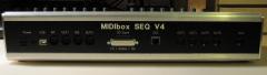
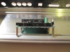
From the album: TK: MBSEQ Aluminium Case
Another view of the backpanel - I consider to swap the positions of Ethernet socket and SD Card/AOUT Extension slot, since internally the SD Card socket clashes with the socket of a LCD -
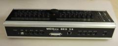
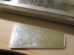
From the album: TK: MBSEQ Aluminium Case
Finally a closed case - hurray! Note that this backpanel has some layout errors as explained in the forum thread. E.g. due to slightly wrong dimensions, the case isn't completely closed (upper screws don't match with the screw threads) -
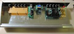
From the album: TK: MBSEQ Aluminium Case
After all modules have been mounted... -
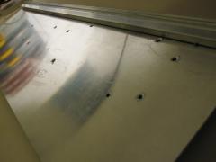
From the album: TK: MBSEQ Aluminium Case
3mm holes have been drilled for all modules. The holes have been deburred with a 5mm drill -
From the album: TK: MBSEQ Aluminium Case
I glued 5mm standoffs to the front mounting holes of the MBHP_ETH module - no screws can be used, but the construction seems to be stable -
From the album: TK: MBSEQ Aluminium Case
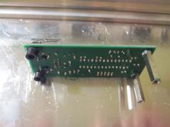
Preparing the core module for mounting -
From the album: TK: MBSEQ Aluminium Case
Due to special request: this picture shows the slots of the sidepanel -
Unfortunately DIN7 sockets are not available at Reichelt anymore, therefore I've to change the spec: use a 8pin socket Reichelt Order numbers: MABP 8SN for the print socket, MAS 80SN for the plug Best Regards, Thorsten.
-
MIDIbox Link won't work for the MBLC protocol. As already mentioned, the protocol requires individual MIDI IN and OUT ports. Thats predefined by all DAWs which support it... This means, that you have to use a MIDI Interface with at least 3 MIDI INs and OUTs (such as GM5x5x5, it gives you two free MIDI IOs in addition) When you are using the search function you will find a lot of threads around MIDIbox LC topics (sometimes the shortcut MBLC is used) Best Regards, Thorsten.
-
The sidepanels have slots as well. yes I got it as a .pdf file, and I don't know if the original format was a DXF file - is a DXF really required? (I don't want to bother Heidenreich too often with such special requests...) Best Regards, Thorsten.
-
Here are the exact measures: http://www.ucapps.de/midibox_seq/mbseq_case_measures.pdf Best Regards, Thorsten.
-
Could you please explain what you mean with "active leg"? And why do you mention a "ground leg"? No leg should be connected to ground... Proposal: use the beeper of your multimeter to check your button. You need two contacts of this button. The contacts should be closed (-> BEEEP) when button is pressed, and opened (-> no beep) when button is not pressed Connect one contact to the DIN module (together with the contacts of the other 3 buttons), and one contact to the anode of the diode. Best Regards, Thorsten.
-
By connecting ground to a row button, all four button functions will be activated at once... Only the periodic scan realized via DOUT pins ensures that a single button press can be detected. However, on the other hand: if it worked this way, it means that your buttons are (or were) connected correctly, and that the issue is between buttons and DOUT pins. Yes, of course! This is the error! Best Regards, Thorsten.