TK.
-
Posts
15,261 -
Joined
Content Type
Profiles
Forums
Blogs
Gallery
Everything posted by TK.
-
Hi Igor, I can confirm that this is a firmware bug (assignment value is masked incorrectly) Sometimes 1..4 will be displayed, sometimes 5..8 - but the actual assignment will always be 1..4 It will be fixed in the upcoming version. If you mean dependencies between HH, Snare and Cymbal sound: yes, they are using the same oscillator, therefore they influence each other. If you mean another drum instrument: could you please attach a .mp3 sample of this random sound? Best Regards, Thorsten.
-
In addition the "GSA" (Gate Stays Active) flag should be set in the OSC menu, otherwise you won't hear any sound at the release phase of the envelope Best Regards, Thorsten.
-
It should work if you change it to a 17" panel (resp. if you reduce the sides which are used to mount the panel into a 19" rack) Currently I cannot confirm your changes as I'm waiting for input from Heidenreich. Background: I made some errors with my backpanel. The "rectangle in rectangle" wasn't specified correctly, so that only 1 mm of the border has been milled away instead of 2 mm. As a result it wasn't possible to plug the panel into the slots. Fortunately I was able to fix this with a file... Thereafter I noticed a misadjustment of the panel by ca. 1 mm, which doesn't look so nice. My tools are not good enough to measure dimensions with such an accuracy. And maybe it's better to have a frame of 1.5 mm at top/bottom (but not left/right side) instead of 1 mm... Therefore I have to redesign the layout based on the exact specs from Heidenreich, and probably should order a second prototype before publishing the .fpd file to ensure that you won't do the same errors. I also want to say: I'm the wrong person to ask for confirmation - somebody with more experience should do this! ;) The good news: mounting of internals is almost finished, pictures soon! Best Regards, Thorsten.
-
The current situation is still unclear - could you please answer to my questions? Best Regards, Thorsten.
-
Hi, since the Logic Control Protocol requires individual MIDI ports for each set of 8 faders, and since the core module can only control 8 motorfaders anyhow: 24/8 = 3 Best Regards, Thorsten.
-
It's normal that you won't measure 5V at an DOUT pin which is used to control a LED and/or button matrix with a common multimeter, as the output patterns are changing with high frequency. And even worse: if somebody would tell you the voltages that he measures at J4 with his multimeter, you would measure different values with your multimeter - because multimeters are just not made to test waveforms... By reading this thread is hard to understand the current state - are the buttons working? (does the menu page change when a button is pressed?) - are the LEDs working? Is only a single LED enabled (thats the expected behaviour) or are multiple LEDs enabled (this would indicate a wiring error). Sometimes you are asking if the schematics are correct, or you are asking questions (such as "ground connection?" or "cathodes before resistors?") which are definitely documented in the schematic (to answer these questions: no and yes) I can confirm that the schematics are correct! http://www.ucapps.de/midibox_fm/mbfm_din_default.pdf http://www.ucapps.de/midibox_fm/mbfm_dout_default.pdf Best Regards, Thorsten.
-
This feature is already provided by MBSEQ V4 (press SELECT button in Manual Trigger menu), but there is no free memory in the PIC based V3 firmware to add it as well (and I wouldn't be able to test it anyhow...) Best Regards, Thorsten.
-
The values of the original SID spec have rounding errors (consider that the spec has been written around 1982...) E.g., take 274 for C0 as an example. Multiplied by 12th root of 2 (=1.05946) makes 290.293, rounded: 290 and not 291 Thats btw. one of the reasons why MBSID sounds better compared to other SID synths ;) It's your own decision if you want to re-calculate the lower frequency values as well. It isn't so much effort... Best Regards, Thorsten.
-

AIN would also accept 100kOhm poti inst. of 10kOhm?
TK. replied to fairplay's topic in Parts Questions
probably nobody tried this with a stm32 before. there is the danger for even more jitter due to the reduced voltage range (0..3,3v)... but stm32 has much more internal sram than a pic, so that it would be a no brainer to add individual resolution parameters for all AIN inputs. however, i will try a 100k pot and report results once i'm back home (next week, so early enough before october ;) best regards, thorsten. -
AIN would also accept 100kOhm poti inst. of 10kOhm?
TK. replied to fairplay's topic in Parts Questions
according to the pic datasheet the input resistance shouldn't be higher than 10k, on the other hand i know that people used 100k joysticks before and didn't complain. it could happen that sometimes (e.g. depending on ambient conditions like temperature, etc.) CC values will start to jitter, but mostly this doesn't really hurt (e.g. as long as your application doesn't start to record automation data on value changes). adding a 11k resistor in parallel won't help (leads to nonlinear curve), reducing resolution would help to avoid any jitter, but i would propose to start with the default resolution. best regards, thorsten. -
Change modify DIN table on MBFM for button assignment
TK. replied to Echopraxia's topic in MIDIbox FM
this isn't possible, as the button handler is tailored around the matrix handling. you would have to implement dedicated button handlers for each button function, but there isn't enough free memory in the firmware. it's better and much easier to get your matrix issue fixed at hardware level. best regards, thorsten. p.s.: what do you mean with "can't get the interrupt service routine working"? did you already modify the firmware? if yes: why and where? -
A nice idea - I haven't considered such possibilities yet since MIOS8 was always restricted on RAM limitations. Note that the same concept can be used to drive a LED matrix - e.g. set DOUT_NUM_BUFPAGES to 8 and output (1 << counter) to an additional DOUT register. If you are working on an extension on MIOS32, you could consider this usecase as well. Best Regards, Thorsten.
-
The distance between DIN7 and MIDI connectors is not correct, it seems that you added the size of the clip at the left side by accident: Best Regards, Thorsten.
-
MIDIbox of the Week (MIDIbox SEQ V4 of sineSurfer)
TK. replied to sineSurfer's topic in MIDIbox of the Week
I must say that I'm really impressed about this nice woodwork - very well done! :) Once I got the wordpress blog fixed, I will publish the pictures :) Best Regards, Thorsten. -
MBSEQ V3 stores global settings (which are not part of a pattern) into internal EEPROM, address 0xf0000200 upwards. No configuration data is stored in flash. You are using the SysEx request for a PIC18F452 which only contains 256 byte. For the 1k EEPROM of PIC18F4620 following request should work: F0 00 00 7E 40 00 01 20 00 01 00 F7 Best Regards, Thorsten.
-
The long summer break is over and I continued with MBSEQ development :) Beta24 is available now: o support for OSC (requires MBHP_ETH module) 4 OSC ports are available, currently they only send MIDI packets. A MIDI<->OSC proxy is currently only available for MacOS (on request) An easy to use Juice based Proxy is planned and will be released soon. (Firmware-)configurable OSC packets will be available in one of the next releases. o new network configuration page for the MBHP_ETH module o the debug terminal now supports a "network" command to retrieve the current status of the network configuration. o now we have global configurations which are stored independent from the session configuration in the "/MBSEQ_GC.V4" file Following parameters have been moved to this file: - MetronomePort - MetronomeChannel - MetronomeNoteM - MetronomeNoteB - RemoteMode - RemotePort - RemoteID - BLM_SCALAR_Port - ETH_LocalIp - ETH_Netmask - ETH_Gateway - ETH_Dhcp - OSC_RemoteIp - OSC_RemotePort - OSC_LocalPort o probability parameter now incremented correctly in edit page o if the track plays multiple notes, gate is only cleared if all notes are set to "---" o BLM: triggers now displayed correctly in all stepviews [/code] The new network configuration page can be found at the end of the menu pages list (press EXIT button, scroll the list to the end) One issue isn't fixed yet: you will find it in the TODO list at the end of the CHANGELOG.txt file. Here some technical notes: [code]The handling of loopback tracks differs from normal tracks. MIDI Events are sent immediately to the transpose/arpeggiator function instead of using the scheduler, so that note changes take place immediately and independent from the track number before new MIDI events are scheduled. Disadvantage of this method: note off events won't be generated, accordingly the gatelength won't be considered and HOLD/RESTART of transposed tracks won't work as expected. Possible solution: gatelength counter for note off events, only used for loopbacked tracks. Problem: how should polyphonic loopback tracks be handled? It could be sufficient to call SEQ_MIDI_IN_ResetTransArpStacks(<bus-number>) depending on the gatelength So - a proper solution will need some time, because I'm currently not sure about the side effects. Best Regards, Thorsten.
-
Please move the BLM connector to the left side of the PCB! :) (-> right side of the backpanel) Best Regards, Thorsten.
-
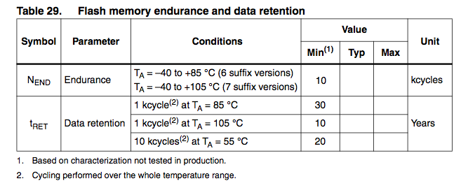
According to the datasheet STM guarantees 10k cycles at typical conditions (55°C) for 20 years Best Regards, Thorsten.
-
Not yet, but currently it isn't relevant. It's only important that the socket can be mounted and soldered. You could add a 7-pin SIL header, the connections can be defined later (there is no equivalent socket on the core module anyhow, cables have to be soldered directly at different places) This socket could be used for other purposes as well by people who don't own a BLM. yes, thats allow. yes Best Regards, Thorsten.
-
Nice idea, I'm interested on a board for my MBSEQ :) Proposals: Currently the jumper settings are ID 10, 12, 14, 16 - I would place the first IIC port at the right, and the last IIC port at the left side (ID 16, 14, 12, 10), so that the ports numbers are in the right order if you look to the sockets from the backpanel side if people don't like this order, just add the jumpers again ;) if no jumpers are required, you could also leave out the pull-up resistors and clamp the appr. ID pins directly on Vdd (+5V) would it be possible to consider a 5th DIN socket (but with 7 pins) at the left side for an optional BLM connector? Distance between the IIC sockets and the BLM socket should be one "left out" socket distance between mounting holes and "socket side" should be at least 20 mm (like on the MBHP_CORE_STM32 module), or better: 25 mm for compatibility with the MBSEQ aluminum case add 2 additional mounting holes at the other side for more robustness (it's worth the PCB area) make jumper J2 compatible with J4 of the core module (the middle pin is used for a receive interrupt, but the MIDI IN option isn't used anyhow) See also my backpanel as reference: http://www.ucapps.de/midibox_seq/mbseqv4_backpanel.png Best Regards, Thorsten.
-
Hi, considered that bit #6 will be set on values >= 64, you could write: movlw 0xb0 call MIOS_MIDI_TxBufferPut movlw 0x53 call MIOS_MIDI_TxBufferPut movlw 127 btfss this_value, 6 ; bit 6 is set on values >= 64 movlw 0 call MIOS_MIDI_TxBufferPut [/code] Btw.: you split the range between 0..62 and 63..127, but it's better to split it at 64, since it's exactly the half of the value range. Best Regards, Thorsten.
-
No, I don't have the old code anymore !!!!!! But probably it looked somehow like this one ?????? void ROUTER_Rx_IIC3(unsigned char ptype, unsigned char evnt0, unsigned char evnt1, unsigned char evnt2) __wparam { unsigned char transposed_note; // IIC3: connected to my Yamaha AN1x // lock/release this routing path on SysEx streams ROUTER_LockPathOnSysEx(PORT_IIC3, ptype); // filter clock if( evnt0 == 0xf8 ) return; // apply exactly the routing as documented under http://www.ucapps.de/midi_router/midi_router_default.gif // note: parameters selectable on the UI are not taken into account here // if this is desired, replace constants by router_flags.* variables as in the original router.c file if( ptype >= 0x08 && ptype <= 0x09 ) { if( (evnt0 & 0x0f) == MIDI_CHN16 ) { if( evnt1 < 0x3c ) { ROUTER_Tx_IIC0(ptype, (evnt0 & 0xf0) | MIDI_CHN9, evnt1, evnt2); transposed_note = evnt1 + 2*12; // if value >= 0x80, decrement 12 until we have reached the range <= 0x7f again while( transposed_note & 0x80 ) transposed_note -= 12; ROUTER_Tx_IIC2(ptype, (evnt0 & 0xf0) | MIDI_CHN1, transposed_note, evnt2); } else { ROUTER_Tx_IIC1(ptype, (evnt0 & 0xf0) | MIDI_CHN13, evnt1, evnt2); } } } // forward data (also) to the Core MIDI OUT #if 1 // if no FE if( evnt0 != 0xfe ) #endif ROUTER_Tx_INT0(ptype, evnt0, evnt1, evnt2); } [/code] Best Regards, Thorsten.
-
Yes, the released code always contains the current routing I'm using by myself. I don't see a need for keeping the diagram up-to-date, since every user would adapt the routing for his own requirements anyhow. I'm not sure if you are asking for somebody who programs the code for you, or if you just only wanted to mention the differences. If you need a different implementation, you could consider to customize the routing as you really need it - the routing in the diagram is only an example, there are many more possibilities. Best Regards, Thorsten.
-
Good to know that this is really not related to a firmware issue (I already feared that my AOUT_NG is somehow different from others...) Attached you will find a modified version of the mbhp_core_stm32_module IO check application. Before upload remove the AOUT_NG module from J19. I reduced the list of pins which are checked to J19 IOs: static const io_pin_t io_pin_table[] = { { "PB5", GPIOB, GPIO_Pin_5, (1 << EXPECTED_FAIL_IPL) }, // On-Board Pull-Up connected { "PB6", GPIOB, GPIO_Pin_6, (1 << EXPECTED_FAIL_IPL) }, // On-Board Pull-Up connected { "PB7", GPIOB, GPIO_Pin_7, 0x00 }, { "PC13", GPIOC, GPIO_Pin_13, (1 << EXPECTED_FAIL_IPL) }, // On-Board Pull-Up connected { "PC14", GPIOC, GPIO_Pin_14, (1 << EXPECTED_FAIL_IPL) }, // On-Board Pull-Up connected }; [/code] It automatically detects shorts on the board and sends error/debugging messages to the MIOS terminal (-> MIOS Studio). Checks will be done with a period of 5 seconds (not immediately) And now the trick: just use a cable between Vss and a J19 data pin to force a short - the application should notify this. If you don't get a notification, you know that the connection between STM32 and J19 doesn't exist (-> open, e.g. bad soldering) If you always get a notification for certain J19 pins, you know that there is a permanent short (-> check solderings between these pins) Best Regards, Thorsten. j19_check.hex