TK.
-
Posts
15,261 -
Joined
Content Type
Profiles
Forums
Blogs
Gallery
Everything posted by TK.
-
I opened a separated forum section for discussions about the MIDIbox BLM, since this project is not tightly coupled with the MIDIbox SEQ project, but can also be used standalone. Schematics: mbhp_blm_scalar.pdf the "BLM_SCALAR" module mbhp_blm_scalar_module_interconnections.pdf interconnection diagram. 5 x BLM_SCALAR modules are required for a complete BLM16x16+X mbhp_blm_map.pdf the mapping between BLM_SCALAR and Buttons/Duo-LEDs. I'm not planning to layout the PCBs by myself, but volunteers already evinced to help out! :) Just start to coordinate your efforts here. Some input from my side: as you know I created the BLM16x16+X on veroboards (link to Gallery) For me this was less time consuming than layouting and ordering PCBs, especially since at the time where I started this project it wasn't clear if the SRIO hardware will work stable - I used tricks that I never tried before to reduce the chip count. With the prototype I've proven that the concept is working, so that I can release the schematics for layout. If somebody really plans to build the circuit on verboard like me instead of waiting for the PCBs, be warned that you need some soldering experience, a lot of time and especially patience! It took me ca. 40 hours to complete the BLM16x16+X on verobards. It was hard work and I would never do this again! ;) With PCBs I expect only ca. 15 hours work, a more stable construction, and less risk for wiring errors (-> newbie friendly). My costs so far (all parts ordered at Reichelt): LED 5 RG-3 Duo-LED, 5mm, 3pin, rot / grün 300 45,00 Euro TASTER 3301B Kurzhubtaster 6x6mm, Höhe: 9,5mm, 12V 300 30,00 Euro 1N 4148 Planar Epitaxial Schaltdiode, DO35, 1 300 6,00 Euro To speed up the wiring I used "verowire" (german: "Fädeldraht"), and I used 7 x "H25PR200" veroboards which won't be required for a PCB based solution, therefore they are not listed in the list above. I strongly recommend you to order 300 LEDs/Buttons/Diodes as well although only 289 are used. E.g., at my order Reichelt only sent me 296 LEDs instead of 300 - good that these were spares! I had the remaining components for the 5 BLM_SCALAR modules + 1 PIC based MBHP_CORE already in my "personal stock". If you are interested in the part numbers you will find the references at the MBHP_DIN and MBHP_DOUT page. Layout suggestions: in the last months I got some mails about how a BLM layout could look like, and this only showed me that it will be very hard to find a universal solution. E.g., somebody proposed to prepare the layout for different button footprints. My comment: due to the increased amount of drill holes this will lead to much higher costs for everybody. Somebody else proposed to use RGB LEDs instead of Duo-LEDs, since they are cheap at EBay My comment: this will increase the costs for everybody again, and it will be hard to find the same LEDs at such a high amount. E.g., consider only 30 people would like to join the PCB order - they would have to find ca. 8700 RGB LEDs from the same seller, or some of the people would have to buy more expensive RGB LEDs from a regular electronic shop. Another point that needs to be considered: for the BLM16x16+X I already chained 15 74HC595, MIOS8 supports 16 DOUT shift registers maximum. Increasing the amount of DOUT registers to control the blue LEDs will lead to difficult software changes. Third point: RGB LEDs draw much more current, especially more than Red/Green LEDs. Blue LEDs probably require additional transistors (or ICs) as source driver. The additional 74HC595 and these source drivers will require a different BLM_SCALAR module - again it doesn't make sense to bring this into an universal layout that is intended for my original project. I'm sure that most people will be happy about a cost efficient solution with Red/Green colour LEDs (like me). Buttons: this will also become a difficult topic. I will use these ones: But I'm not sure if this construction will be stable enough. A better solution could be the usage of the same buttons and caps that where used on Wilba's MBSEQ frontpanel. Partitioning the PCBs: the SRIO and BLM circuit has already been separated. The SRIO boards are stacked under the BLM board. It has to be considered if a huge BLM board is better than splitting the circuit into two or three parts (think also about the reduced shipping costs...) For the BLM_SCALAR boards I recommend separate modules for each 16x4 matrix, because it is too difficult to plug the board into more than 2 large dual pin header sockets. Note that this approach would also allow you to use the same BLM_SCALAR boards for different BLM board designs! Matrix routing: can be changed if really required. The firmware has to be adapted accordingly (changes are difficult for somebody who never worked with forward/backward matrix transformations before, see main.c) Therefore changes in the routing are only recommended for people with software programming skills. Additional features: I will add 6 faders to my BLM16x16+X, because I find it important to get the possibility for manual sound changes with one hand, while sequences are changed with the other hand (therefore it's better to have the close to the matrix). The firmware is prepared for up to 8 pots/faders. More informations/suggestions on request. However, my hope is that this will become a community project where experienced people will help out and where I don't need to support you that much! I could be interested to join the PCB/kit bulk order as well! :) /Update Oct-2015: after 5 years finally we got a kit created by Latigid On! -> http://midibox.org/forums/topic/19736-blm-16x16x-build-guide/ /Update Jan-2016: new firmware blm_scalar_v1_1 can be downloaded from http://www.ucapps.de/mios_download.html It contains prebuilt hex files for various hardware configurations: o project_without_ain.hex -> without AIN enabled (use this if J5 pins not connected to ground) o project_with_4_mapped_ains.hex -> for Latigid On's BLM PCB layout, only 4 faders used o project_with_4_unmapped_ains.hex -> AIN pins are mapped 1:1 o project_with_8_mapped_ains.hex -> for Latigid On's BLM PCB layout if 4 faders + 4 extension AINs are used o project_with_8_unmapped_ains.hex -> AIN pins are mapped 1:1 /Update Jan-2016: if you are using a PIC18F452, it's required to change the PIC device configuration while flashing the bootloader: the brown out reset level has to be changed from 4.5V to 2.7V as shown in this picture: Otherwise PIC could be reset sporadically (depending on the number of enabled LEDs) because the voltage level could fall below 4.5V! This change is only required for PIC18F452, other pics (such as PIC18F4620 and PIC18F4685 will work w/o this change). Unfortunately this change can only be done with a PIC programmer. Please contact me for the case that you don't own a PIC programmer. I could send you a replacement PIC18F452 Alternatively use a PIC18F4620 or PIC18F4685 if you own one Best Regards, Thorsten.
-
Thank you for the great feedback! :) For discussions about the construction (and coordination for PCBs/kits) I created a new forum section: http://midibox.org/forums/index.php?/forum/43-midibox-blm/ I used virtual instruments that are part of Logic Studio 9: Mostly presets, but with modifications to harmonize the sounds. + Stylus RMX as a drum sampler (I don't use the beatslicing mechanisms): They are already working together. MBSEQ V4 directly controls the LEDs and receives button changes. Whenever a track or step or mode or whatever is selected on the BLM, MBSEQV4 directly jumps to the appr. edit screen so that step informations are displayed and values can alternatively be changed with the common control surface. :) The same vice versa: if you select a velocity, length, CC or similar parameter layer, the value can be modified on the BLM16x16 as well (but only with 4 bit resolution per step of course) This for example allows you to draw waveforms :) Best Regards, Thorsten.
-
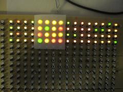
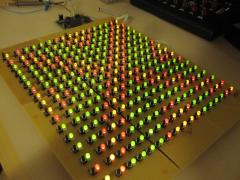
MBSEQ V4 remote controlled by my new Button/Duo-LED matrix prototype. The frontpanel hasn't been created yet, and it's difficult to push the mini buttons without button caps. But playing with this toy is already a lot of fun! :) The BLM firmware is running on a dedicated PIC based core module and communicates with MBSEQ via MIDI. The optimized protocol is fast enough to achieve high refresh rates between 350 fps (if only a single line is changed) and 20 fps (if all 512 LEDs are changed). Best Regards, Thorsten.
-
Finally I was able to reproduce this - the MIDI clock was sent to the non-existent USB5..USB8 ports, and Live mapped these ports to USB4 It will be fixed in Beta21. Best Regards, Thorsten.
-
Hi Trevor, that's ok for me :) Best Regards, Thorsten.
-
My plan is to give each button a useful function. But you are always free to remove functions that you don't like and to add your own code. Some programming examples can be found at http://svnmios.midibox.org/filedetails.php?repname=svn.mios32&path=%2Ftrunk%2Fapps%2Fsequencers%2Fmidibox_seq_v4%2Fcore%2Fseq_blm.c No problem. :) Best Regards, Thorsten.
-
It's already implemented as alternative function for the metronome button (press MENU + METRONOME) Unfortunately you haven't told us if you are using V3 or V4, this makes it difficult to give you an explicit help :-( MBSEQ V3 users: If you want to use the METRONOME button to directly access this function (w/o pressing MENU), replace DIN_ENTRY SEQ_BUTTON_Metronome, 1, 3 [/code] by: [code] DIN_ENTRY SEQ_BUTTON_ExtMIDIStart, 1, 3 in your setup_*.asm file If you want to assign a different/additional button, just add a new button entry with the appr. SR and pin number MBSEQ V4 users: edit this entry in your MBSEQ_HW.V4 file on SD Card BUTTON_EXT_RESTART 0 0 [/code] Best Regards, Thorsten.
-
Isn't it great to have 4 independent USB ports that give you access to up to 64 MIDI channels? ;) Use models: you want to generalize/improve the routing inside your DAW, or you are using a Windows PC and want to send MIDI data to different programs w/o using virtual MIDI ports to split the streams. If you don't see any use for 4 USB MIDI ports, always use USB1 and ignore the others. Probably you selected a pattern for group #3 that was previously pre-initialized for group #2 The MIDI channels can be configured in the EVENT page - they are not strictly tied to the group or track number, but free configurable and stored in the pattern itself. This gives you highest flexibility (e.g. different patterns can send to different ports and MIDI channels) Best Regards, Thorsten.
-
I real giant frontpanel (* :drool: But there are some things that need to be considered: you placed the BLM at the top of the panel, which means that when you are pushing buttons you won't see the LCD output. But for some BLM modes it might be important to get a direct response from the LCDs. Therefore I propose to place the BLM below the common control surface. The 16 "extra column" and 16 "extra row" (I haven't found a better name yet) buttons/LEDs are missing. They are important to select modes/tracks/step views and maybe other features (like loops, sections, parameter/trigger layer, octaves, special effects) directly. Also the "shift" button is not there (lower left corner of my BLM16x16+X) - thats one of the most important buttons to control the entry. E.g., pressing SHIFT will allow you to select the BLM mode with the 16 "extra column" buttons that are normaly used to select and mute tracks. It will allow you to accent steps with the BLM in pattern edit mode. etc. Currently I'm in the progress to implement the BLM modes and to find an intuitive interaction scheme. Once most of the modes have been implemented and I'm happy with the solution, I will finalize my own frontpanel (e.g. adding labels to the extra buttons) and document the project. So long I haven't reached this state, I can only recomment: be patient please and design your frontpanels based on my specs, otherwise you won't be able to use most of the features later! (I'm not willing to implement alternative solutions for reduced BLMs, because it would be too much work and the usage would be really ugly - so cumbersome like on most monome apps ;)) I will document the schematics in the next days and start a separate topic for this. Basically it consists of 5 chained "BLM_SCALAR" modules that are documented here: http://svnmios.midibox.org/listing.php?repname=svn.mios&path=%2Ftrunk%2Fschematics%2Fmbhp_blm%2F (but note that the Jx sockets are combined now to two 2x10 sockets) A schematic which documents the matrix construction (connections between rows and columns) isn't available yet. It requires a PIC based MBHP_CORE module with the "blm_scalar" firmware: http://svnmios.midibox.org/listing.php?repname=svn.mios&path=%2Ftrunk%2Fapps%2Fcontrollers%2Fblm_scalar%2F I consider a PIC18F4550 based USB option as well, but I'm not sure if this is really for interest... Communication between MBSEQ V4 and BLM is done via MIDI. The protocol is documented in the README.txt file of the application - it's really fast! And it's generic enough so that the BLM could be controlled from other applications (e.g. PC/Mac based) as well. The MBHP_CORE_STM32 module has some spare "midi" Rx/Tx ports available on the JTAG connector, one of them will be used so that no common MIDI IO pair has to be sacrificed. Thats all for now. My BLM is running very stable btw. - I'm surprised a bit because I expected a) a higher current consumption and b) issues with the shared DOUTs as line control driver for LEDs and buttons (the only solution to reduce the DOUT chain to 15) - but it works :) If somebody could create a PCB for the matrix (once schematics are available), it would be very helpful. Best Regards, Thorsten.
-
Don't worry, all 100 nF caps only exist to meet certain design rules, but your sammichSID will perfectly work even if they are not stuffed. If you want to feel better, you can use *any* 100 nF cap that is available in your local electronic store, there is no need to spend some $$ for mouser shipping costs. Best Regards, Thorsten.
-
The conversion in DEBUG_MSG is wrong. Instead of: DEBUG_MSG("%d.%03d", (int)totalValue, ((int)totalValue*1000) % 1000); [/code] write: [code] DEBUG_MSG("%d.%03d", (int)totalValue, (int)(totalValue*1000.0) % 1000); Best Regards, Thorsten.
-
Yes! But to keep the float resolution, you should write: float totalValue = (float)decValue / 1000; [/code] or better (I don't know if this really makes a difference, but I always add .0 to float constants to force the correct type): [code] float totalValue = (float)decValue / 1000.0; Best Regards, Thorsten.
-
It could be important to cast a value to the correct type before doing such operations. A code snippet would help to understand what is going wrong. On the other hand: If your value is an Int anyhow, and you only want to reduce the resolution to get a 7bit value, why not using "intValue / 1000"? Float operations are expensive (performance wise), but fixed point divisions (and multiplications) of integer values are fast since they are supported by the hardware. Best Regards, Thorsten.
-
Everything correct. Possible errors: - Jumper J26 not stuffed - Resistor Array R32 not stuffed - wrong wiring between CORE_STM32::J19 and AOUT_NG - +/- 12V not connected to MBHP_AOUT_NG module (you could measure the low range voltage of the TLV chip directly at JP1 and JP2, see schematic) - JP1/JP2 jumpers of AOUT_NG module not stuffed When testing the CV voltage, the sequencer should play *different* notes (otherwise you won't notice a change) e.g. with c-1, C-0, C-1, C-2 the CV channel should output 1V, 2V, 3V and 4V Best Regards, Thorsten.
-
I know the location and some of the guys... ;) The projections are very impressive, well done! Best Regards, Thorsten.
-
There is a simple answer: the simplified (s)printf function of MIOS32 doesn't support %f See also http://svnmios.midibox.org/filedetails.php?repname=svn.mios32&path=%2Ftrunk%2Fapps%2Ftutorials%2F003_debug_messages%2FREADME.txt Workaround: write DEBUG_MSG("%d.%03d", (int)floatValue, (int)(floatValue*1000) % 1000); Best Regards, Thorsten.
-
I remember that Kurt did something similar, but without SID based sound output. Here a link to the documentation and a video: http://www.midibox.org/dokuwiki/doku.php?id=mblight_mind-machine Of course, it could be possible to output sound as well. MIOS doesn't prevent you from implementing something like this ;) Best Regards, Thorsten.
-
You don't need to recompile the firmware. Just edit your MBSEQ_HW.V4 file on SD Card: # define the AOUT interface which is connected to the core # 1: a MBHP_AOUT module # 2: up to 4 (chained) MBHP_AOUT_LC modules in 8/8 bit configuration # 3: a MBHP_AOUT_NG module AOUT_INTERFACE_TYPE 3 [/code] unmount the SD Card on your PC or Mac and reboot the core to reload the file. Ensure that you are using the latest firmware release. The AOUT_NG module wasn't working in Beta19, I fixed the driver and tested the AOUT_NG module in the latest beta20 release (as documented in the ChangeLog) Best Regards, Thorsten.
-
Follow the progress of the BLM16x16 (+X ;-)) project
-
-
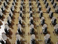
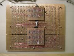
From the album: TK: BLM16x16 + X
-
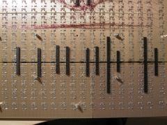
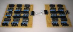
From the album: TK: BLM16x16 + X
-
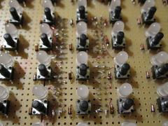
From the album: TK: BLM16x16 + X
-
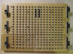
From the album: TK: BLM16x16 + X
-
From the album: TK: BLM16x16 + X
-
From the album: TK: BLM16x16 + X
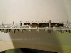
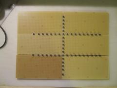
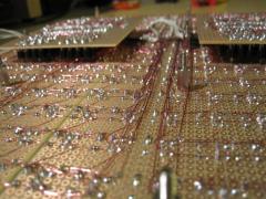
Please note: soldering such filigree wires is time consuming and requires some dexterity. It will work perfectly with double layer PCBs, but if you really consider to build the BLM on a prototype board like me, it's probably easier to add sockets at the bottom of the PCB (thats my conclusion after all the work)