How to Offset and Scale an Analog Input
When interfacing a Joystick, Modwheel or Pitchbender it is sometimes found that the voltage range on the potentiometer output is well inside the range of the Core ADC input.
This can often be overcome with digital calibration in the firmware (e.g MIDIbox KB) in some cases there is extreme loss of resolution.
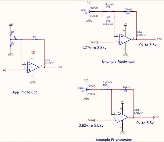
Presented here is a circuit to overcome this to give the ADC the full range (in this case 0..3.3V) even though the range of the potentiometer is well inside this.
The design process is very easily done following this app note:sloa097.pdf 230.01K 12 downloads
I've done a spreadsheet to make it even easier!Scale Offset.zip 2.45K 9 downloads If you don't have MS Excel, you can use it with free tools Google Docs, or Open Office.
To use the speadsheet you enter numbers into the blue fields. The input range at the top as measured on your pot. In preparing the examples, I played with the value of Rg2 so that Rg2+R1 came close to 10k. This allowed to replace them with a 10k trimpot as in the example circuits. It was just as well, as the trimpot did require some tweaking away from the calculated values, I found.
I chose LM324 op amp as it's output goes down very close to 0V. It's maximum possible output with a Vcc=5V is about 3.5V which should be quite safe with a 3.3V Core ADC such as LPC17 MBHP Core.
There are 4 op amps in this device, so 4 scaling/offset circuits can be implemented with 1 chip.
Here's the circuit with 2 worked examples:

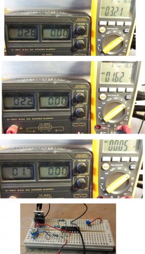
Here's the test (input on left, output on right) showing 3 points (Modwheel example):
Here's another test (input on left, output on right) showing 3 points (Pitchbender example):

-
 2
2


0 Comments
Recommended Comments
There are no comments to display.
Create an account or sign in to comment
You need to be a member in order to leave a comment
Create an account
Sign up for a new account in our community. It's easy!
Register a new accountSign in
Already have an account? Sign in here.
Sign In Now