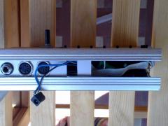
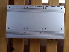
ErMangaver 0 Posted May 5, 2011 On the left side there are the four screws to fix the core PCB (actually only three in the pic), then the screws for the SID1 PCB and next, the last four on the right side, are for the SID2 PCB (only two in the pic). The purpose of the two lower screws (only one installed) is to fix the voltage regulators to the aluminium shell. The shell is indeed both an electrical ground and an heat dissipation help in this case. Also for the heat problem I've done those small holes along the edges of the box but I'm afraid they aren't really enough.


Recommended Comments
Please sign in to comment
You will be able to leave a comment after signing in
Sign In Now