Leaderboard


Popular Content
Showing content with the highest reputation on 02/26/2016 in Posts
-
1 point
-
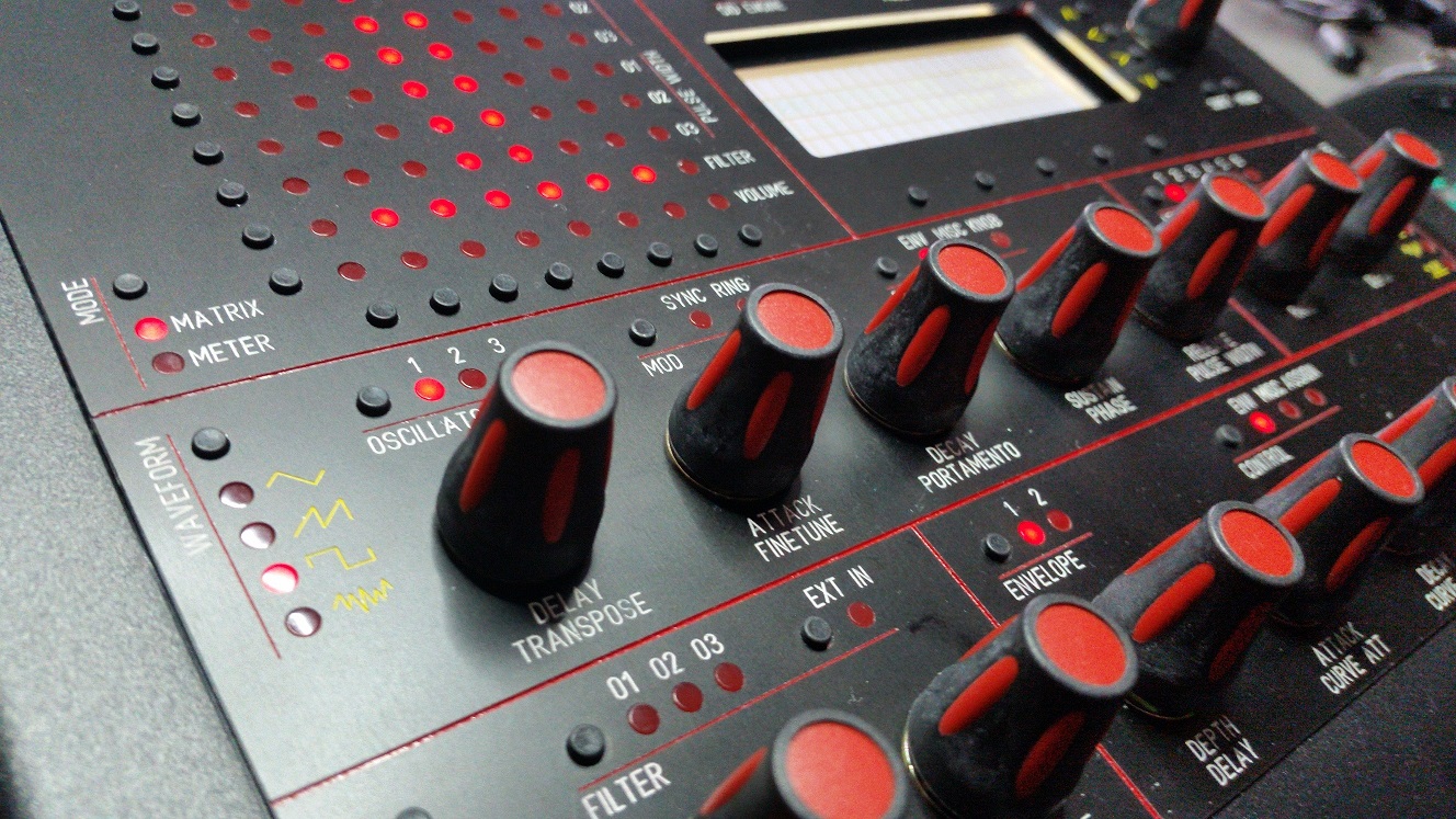
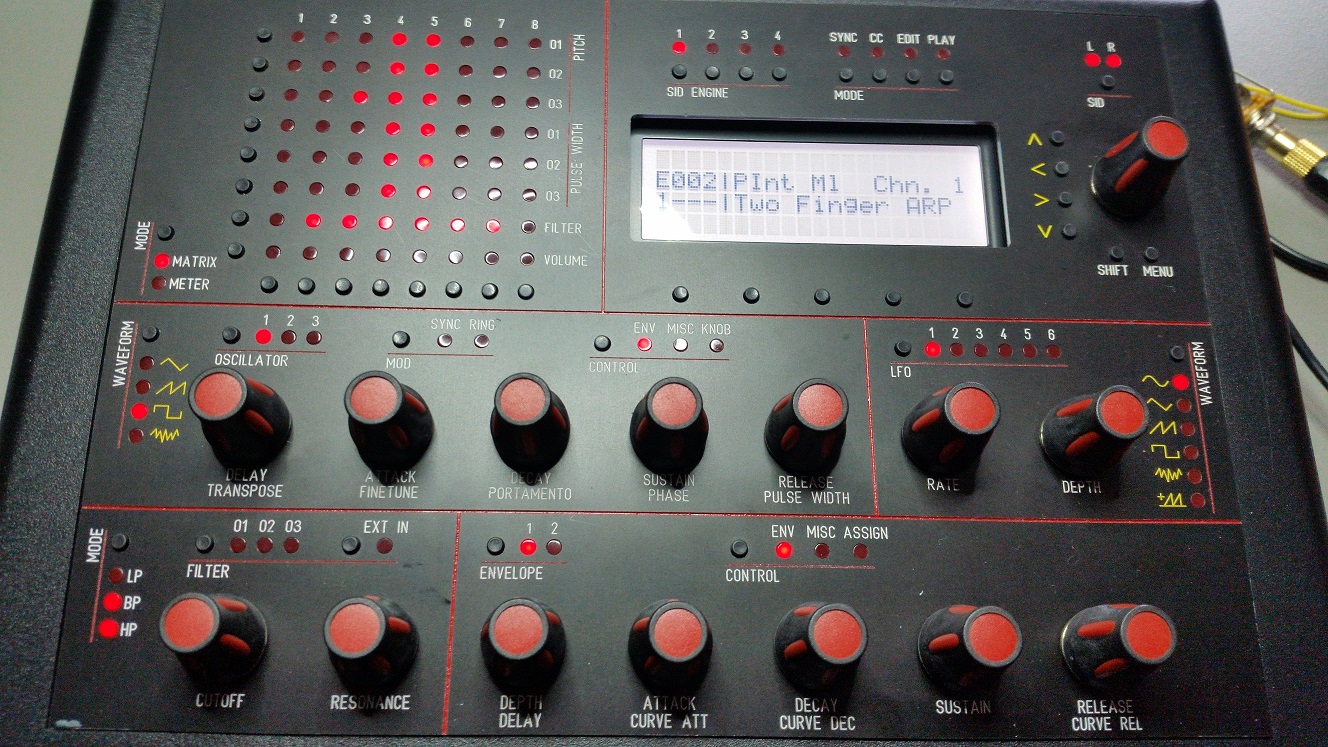
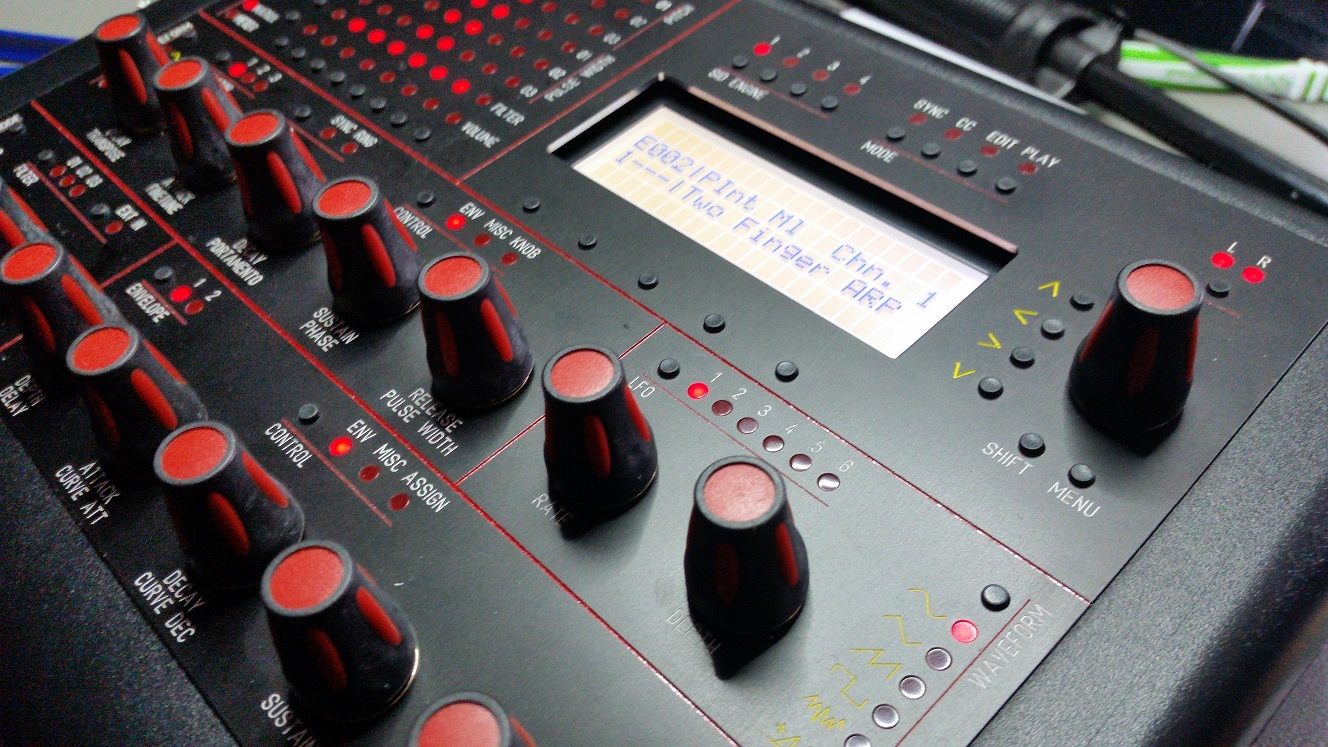
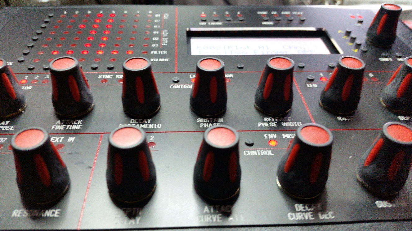
I just finished changing the display and all the leds in my MB6582, and I thought I'll share the experience here, because this is by far the best MB6582 building tutorial I know of, and probably more people will benefit if the following info is here rather than in its own thread. So I had a display where the backlight couldn't be dimmed – either it was broken or it didn't have the ability; anyway there was no problem with the base PCB end, so I got another display, this time red with a negative backlight. Originally I had built the control surface with JB Welded hex spacers and flat top leds. Already when I was first putting it together I found that the flat top leds were not a good idea, or at least not practical: the holes in the frontpanel were quite tight, and it was a major PITA to get all the buttons and leds aligned with the fronpanel holes without any of the leds bending. Anyway, I managed it more or less. One MOD matrix led died in the process, but I didn't feel like opening the panel just for that, so it stayed like it was. However, now that I had decided to change the display, I decided to change the leds as well, and make it more practical this time. However, as I separated the frontpanel from the CS PCB, I found that before I could get down to changing the leds and the display, I needed to solve another problem: almost all of the JB Welded hex spacers were shaky, like teeth that were about to come loose. Only a few seemed firm, so I just picked all of them off and dremeled the inner surface clean of JB Weld. I realised quickly that hot-glue won't work because you need to press the frontpanel to the hex spacers attached to the CS board, but hot-glue will solidify much too quickly, even if you tried to fasten only one hex spacers at a time. In the end I decided to leave the hex spacers out completely and just use the four aligned corner holes in the CS PCB and the frontpanel. My solution is four black countersunk 16mm M3 screws coming through the frontpanel corners, on the inside there's an M3 nut and a 3mm plastic spacer. The Pactec enclosure fastener metal piece is there too (under the nut), even though I have drilled out the threads. (I haven't filed out the "fangs" of the metal piece though.) CS PCB goes on top of this, and the buttons protrude above the surface quite comfortably. I bought four 16mm screws, and it seems like it's the absolute minimum; probably 20mm would have been better, even though 16mm was just about manageable. In addition to the corner screws, the frontpanel is attached to the CS PCB only by having a washer and a nut in the sustain/phase encoder (on the top side of the frontpanel). In my opinion the push-button feel is fine, the PCB doesn't give too much way anywhere, even though the hex spacers are gone. The previous image also shows the countersunk corner screw. Originally the frontpanel didn't have countersunk corner holes, but I used a drill bit and a press drill to make them so. Then I used black marker to colour the bare aluminium for a more uniform black appearance. Then the leds. I desoldered all the flat top leds and used a mechanical suction pump to clear the holes for new ones. Fortunately I didn't lose any pads in the process. I bought "normal" 3mm tinted red leds and put them in place, but this time I soldered them a bit lower than usual so that their "thick parts" don't really go into the holes. This way the frontpanel can be removed much more easily, and in practice you only have to worry about aligning the push buttons with the holes. It would look more cool if they did come out a bit, but from a repair point of view I find this solution far superior to the flat top leds or protruding "normal" leds. I soldered the new leds the same way as Hawkeye in his tutorial: put the leds in place, join the CS PCB to the frontpanel, cover the led holes in the frontpanel from the top with masking tape, and guide the leds into their holes. The tape prevents them from getting too high, and holds them in place to some extent as well. When they are placed in their holes, pick a led group, solder one leg of each led, remove the tape, and if it looks fine, solder the other legs too. One final word on the red negative backlight display: I was surprised that the viewing angle of the display was clearly worse than for the "normal" display I had earlier. The negative backlight LCD is ok from a "sideways" angle (a shallow angle from "left" or "right" side of the display) but sitting straight in front the of the display, a shallow angle either "above" or "below" the display shows very quickly just the red backlight and obscures the text. Fortunately with the placement of MB6582 in my setup this is not an issue, but it could easily have been.1 point