

chapelier fou
-
Posts
47 -
Joined
-
Last visited
-
Days Won
1
Content Type
Profiles
Forums
Blogs
Gallery
Posts posted by chapelier fou
-
-
Wow thank you very much ! i'll keep you informed, and i'll post here the next steps of the project, if i manage to do it as expected.
cheers.
louis
-
Thanks !
That would be good news. I'll get in touch with TK, then !
louis
-
Hi there !
i've made a pedagogical musical installation in a school, called "Végétophone". It's working beyond my expectations and i've been asked if i could make a small series of a suitecase version that would be bought by music schools, libraries and venues. Since it contains a midibox in it i(amongst other things) was wondering if was allowed to do that. It's a purely non-profit project of course.
By the way if you are interested you can watch these :
Thank you !
louis
-
 1
1
-
-
Hey, thank you so much for the detailed answer.
Under the pressure of the emergency, i had to find another solution. So i made a few phone calls and found an arduino Mega, it seems to be easy to do (no midi), so i'll go this way.
But i definitely will build other midibox projects, so i'll eventually sort it out !
Again, many thanks, i really appreciate.
louis
-
Help !
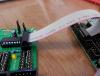
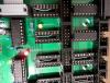
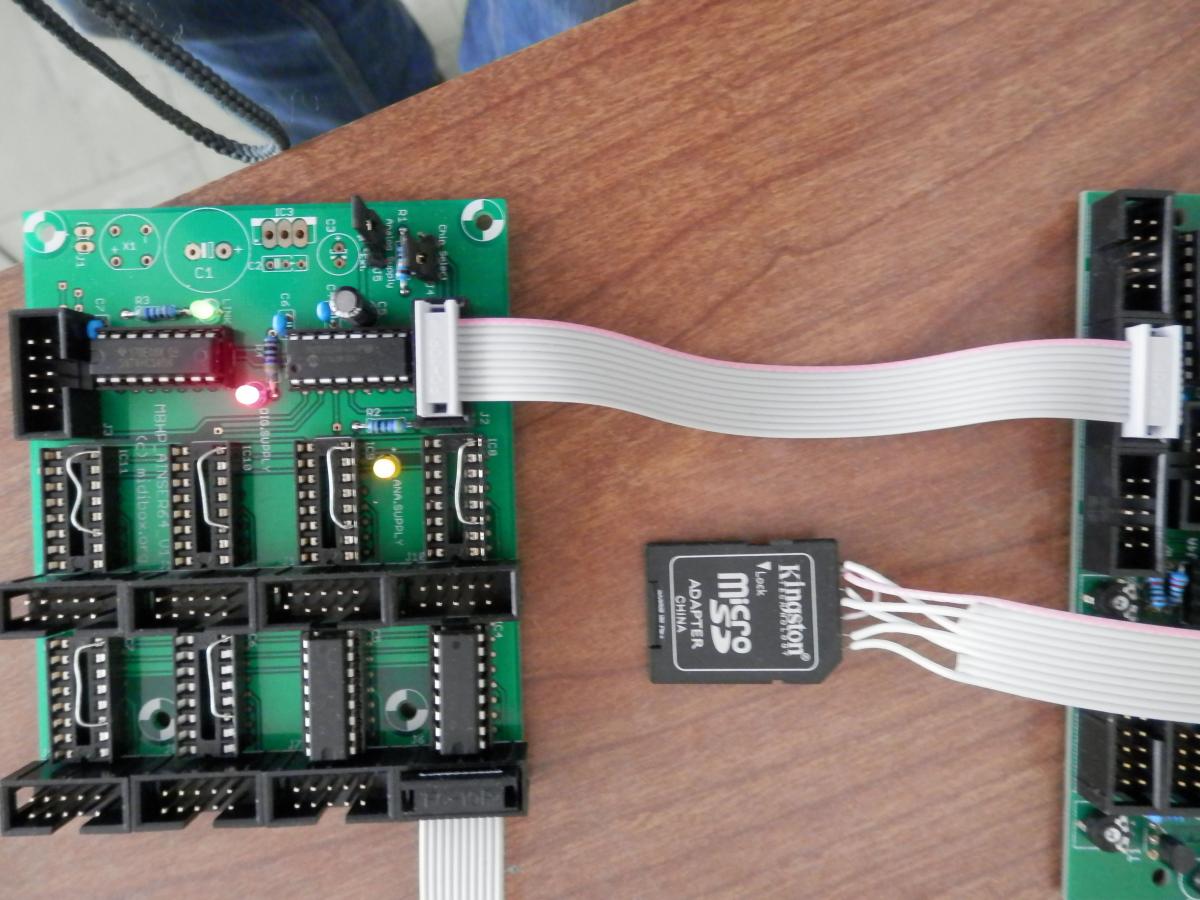
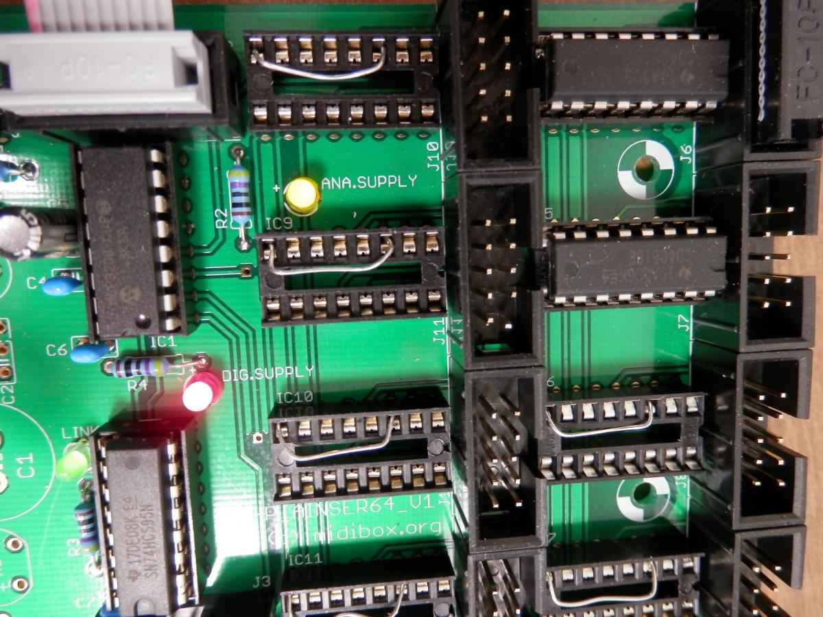
I tried a new cable orientation (see picture) but it behaves the same way...
By mistake i broke one of the MCP3208 pin.... you can see it on the picture as well. But i assume it should work anyway, since this pin is for CH0 (pin1), so it just broke J6, right ? Otherwise, if i find another MCP3208, i can just replace it, or does it need to be flashed ?
Last question : i didn't edit my midi128io settings regarding AINSER, i thought this might be the issue. is it supposed to work by default ? (i don't have any LCD connected so i would edit in openoffice)
This is urgent, very urgent...
Thank you very much
louis
-
Hey thank you for your answer ! By IC1 and IC2 you mean MCP3208 and 74HC595 ? Which pins should i test ? Between 15 and 16 ?
And just to be sure : it should be working even without anything plugged in my analog inputs, right ? (in my case, J6 and J7).
-
double post
-
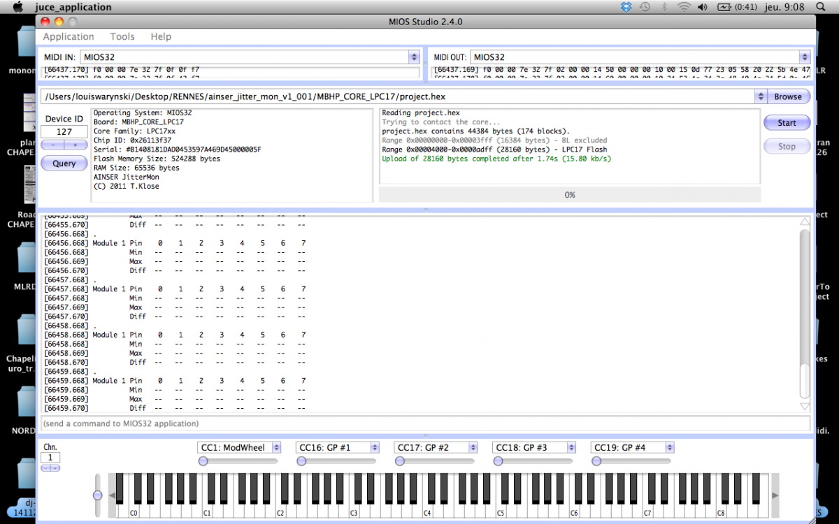
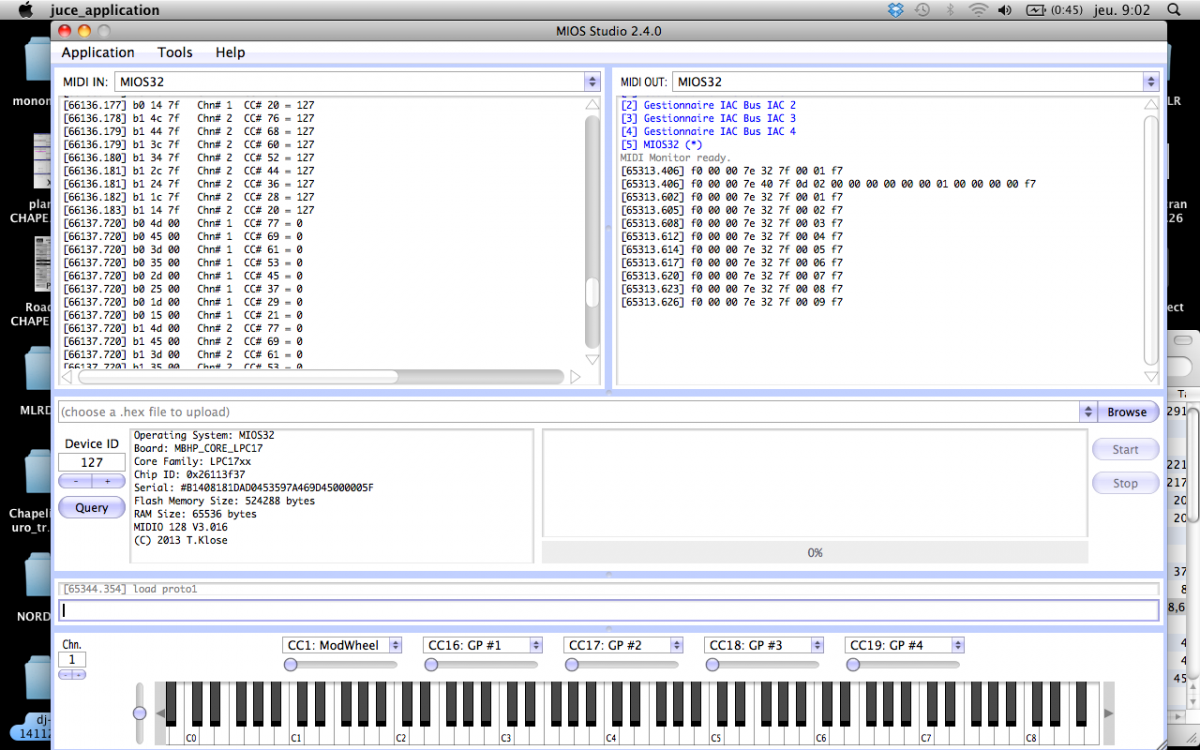
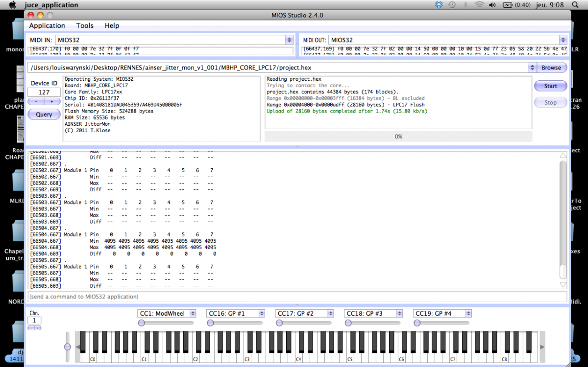
Here are a few pictures and screenshots. Help would be greatly appreciated ! (I should have this working within 2 days to finish my residency in a school....)

-
Hey. Still no luck with version 3.0.16... The link led's on or off state seems pretty random to me. Would it help if i post pictures and screenshots ?
-
Thanks, i'll give it a try tomorrow, since i think i am still on v3.0.12. Hopefully this could be the issue.
The link led never flashed. It's just stays on. Or it just stays off, sometimes. When i plug/unplug/replug the J19 several times, the link led is most of the time staying on, but maybe 20% of the times, it stays off.
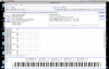
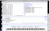
When launching the jitter monitoring app, i've got nothing but -- everywhere. when i unplug the ribbon, i've got 4095 for min and max and 0 diff. when i plug it on, i've got 0 min, --max and 0 diff.
I'll come back here tomorrow and let you know !
-
Thanks,
i mean, it stays lit. sometimes when i start mios studio after plugging the midibox or whatever, it remains unlit. Anyway, it's never been slowly fading. I've tried the jitter monitor application, it didn't show anything (although i'll redo the tests today).
-
Hi,
i'd like to have some help with my AINSER64 used in a MIDI128IO config :
i've mounted the unit, 'shortcuted' several unused inputs. When i plug it to the core, the yellow and red lights light on. But the green 'link' one sometimes remains lit, or unlit. that seems to indicate a problem.
In MIOS Studio, i see a bunch (i guess 64) of CCs going to 0 when i unplug the AINSER. Any idea of what i am doing wrong ?
Thank you,
louis
-
Hi folly !
i'm still waiting for my AINSER64 kit, it should arrive shortly. I'll let you know, but i'm pretty confident, since TK. recommended it precisely for this reason.
I'll post back here.
-
Fixed !
Appears to have a problem with my e-mail address.
-
Thank you, and sorry for posting in the wrong section.
I did contact him without any luck and i assumed it was ok to ask here. My apologies.
-
Hi, i made an order 2 weeks ago,
no news, no reply....
-
i see ! Makes sense !
Well, i'll go for an AINSER 64 then !
Thank you very much for your answer. MidiBox is so great... awesome community as well.
-
As a side note, i've got a lot of parasites when sending a CC. My Pots are 4.7 KOhm with 100 nF capacitors. it looks like the capacitors are not filtering anything.
By parasites i mean many occasional drops to 127, or constant flow of +/- 1 in the CC's value.
Any idea ?
-
Hi !
I want to connect 8 pots to my Midi I/O core.
When i edit a preset file within a table editor, it displays inputs 0 to 5. I would imagine it going from 0 to 7. Can i simply add 2 lines in the table ?
thanks !
-
Got it working ! Chaining DINs and DOUTs works ! Everything is fine now...
Must have miswire some ribbon cable or whatever.... Taking a break before going back on work is sometimes the best thing to do !
Thank you, guys.
louis
-
do you have the DOUT / IN PCBs with 4 registers upon? the ones i got from SmashTV have a DIL 10Pin Header and the DIN are to be connected to the Front Row and the DOUT to the Back Row. DOUT are Connected to J8 and DIN to J9.
did you already see those schematics:
Thanks, yeah, i've seen this. So how are you supposed to wire them from the J8/9 connector ? Split it in two ? Also in this DOUT schematics, the ground line is spotted on J5, but i assume it's on all of them, ain't it ?
Hi Louis,Have you tried to connect only your DOUT chain to the J8/J9 connector and then from MIOS STUDIO typed in the command “set dout all 1†to your LPC17 core and see if this works? I suspect that you have the older DIN card R4 or earlier that has a wire missing to rout the output data thru the DIN card. The following came from the change log of the DIN board R5 from SmashTV.
Routed SO from J1 to J2 (so a DIN:DOUT chain is possible)
To fix this add wires to all your DIN cards on the SO pin. This should allow you to dassy-chain your Din & Dout cards.
Pete
Didn't try this specifically, but did try with only a DOUT connected and played midi notes from ableton live : my led never flashed.
Anyway, thank you very much, it feels like im on the good way, just need to clear my mind and unstress a bit...
Gonna keep you informed ASAP. I let my gear at the school im working in.
-
Hi
I getting desperate...i've assembled my MIDI IO128. Got 4 DOUTs and 4 DINs.
Everything seems to be working, recognized by the computer etc. I can produce notes in with the DINs as expected.
The thing is i want to use the DOUTs to turn leds on and off when receiving notes, but no success. I just don't know how t wire the DOUTs.
The weird thing is that in the MIDI IO128_v3 interconnection diagram, the J8/J9 is split into 2 5 pin connectors. I can link my 4 DINs in series and it works, but no luck with the DOUTs.
Any help ?
thank you
louis
-
Wow, great !!
Many thanks !!
louis
-
Anybody ?

MiDI IO 128 : Pots setup
in MIDIbox User Projects
Posted
Very sorry, i've used midibox only once, and since i broke my AINSER chip, i ended up using an arduino for pots.