

novski
-
Posts
460 -
Joined
-
Last visited
-
Days Won
5
Content Type
Profiles
Forums
Blogs
Gallery
Posts posted by novski
-
-
Dieser geht: Mouser.de; 517-SD-RSMT-2MQ -> LINK
-
 1
1
-
-
Did you pm SmashTV already? He may give you the outlines without top and botom layers if hes not willing to public his work...
-
very nice renderings!
-
You need one MF_NG for 8 Faders. Those MF_NG modules are connected to the Core. So you need a core as well. If its possible to connect two cores together i don't know.
I made a schematic that makes it more clear. All through it was made in thought that four MF_NG (or 32 Faders) will be max...
have a look: http://www.midibox.org/dokuwiki/doku.php?id=fadercore_-_fadermodule_for_audio_daw
best regards, novski
-
Hi soundcheck
First welcome to midibox.
Im shure you are at the right place for your project.
The momentary project MF_NG can handle 32 Faders as you already know.. I don't think anybody jet did a second batch of 32 Faders. Mostly due to cost. So you may be the first. But don't fear. Maybe TK can give you a answer on the purpose of connecting two cores together with each 32 Faders.
What you have to check first is if its possible to connect so many faders to cubase. So im quite sure that the used motormix protocol does not serve more than 32 faders. I think due to some reasons you might want to consider. The Motormix Protocol makes a 14bit tracking resolution upon each of your fader. The most common used Protocol is the Behringer BCF2000 witch tracks your fader with 8bit (my assumption, please correct me if im wrong.) So you see the protocol you use will be important to layout a plan of how to build your controller. I don't know qubase in its newest version.
maybe you can get some informations in the Manual or in the helpfiles.
To the question about the Layers. Im quite sure that is possible with the presets you can program in MIOS.
best regards
novski
-
I don't realy understand. Are you just looking for the Code to adapt it to a selfmade project or are you looking to for a solution to get meters generaly?
Edit: All code is availabe in a SVN Repository: svn://svnmios.midibox.org/mios32 http://svnmios.midibox.org
-
Hi Zam
Can you explain me more bout the advantage of this?
I wold like to help you improve your Faders if i can learn something and maybe use it for my Fadercore afterwards..
br
novski
-
If you open it with a text editor you can read the version number.
Its 6.5 in the case of VLR-8oDispV1.3
can you try to oben it with a demo version of eagle 7.1 or so?
br
novski
-
Yes its opensource. Have a look in to the wiki page. http://midibox.org/dokuwiki/doku.php?id=fadercore_-_vlr-8odisp
-
Just delete/leave out the 16pin connector J0.
-
What do you mean with a "Keypad"?
I don't understand the question...
best regards, novski
-
I think you simply have to choose the midi port in your os... Look in to the preferencies of your program or your os first...
-
Seams like the manual is not complet. There are 6 modes but just one is described...
Midibox is a opensource platform that works with Do it yourself hardware. Your part carrys the same name but is a commercial product.
-
Wold be nice if you wold provide the modified files after tests... Im quite shure there are others that have those displays as well...
The guys that are currently developing the CV v2 might be delighted about that... :-)
br,novski
-
Hi schoko11
All i know is that i have the jumpers of my JY-MCU type of OLED on BS0,1,2 in 4 Wire SPI mode.
And this core pinout on J2 works: http://beb.digitalaudio.free.fr/RTPMIDI_CORE_STM32_Assembly_Guide.pdf
I tested it yesterday with 16 OLEDs.
Best regards
Novski
-
I don't know a way to test else...
This alternative connection (J10B) is only supported by the upcomming CV2 i think and i just had a brief look to the Midibox_CV2 and didn't find a precompiled file.
Im sorry for that confusion...
What app do you use by now? And whats your Bootloader setings?
-
Hi Shaeded
Im haveing some kind of similar problems.
Can you describe what you did and what about the Riboncables was wrong?
Thanks
novski
-
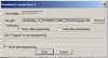
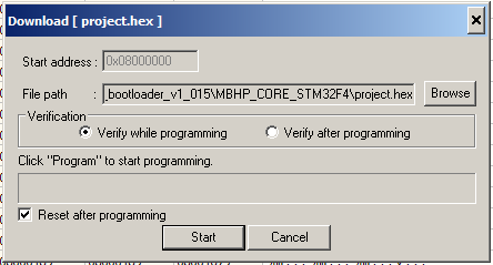
Hi TK
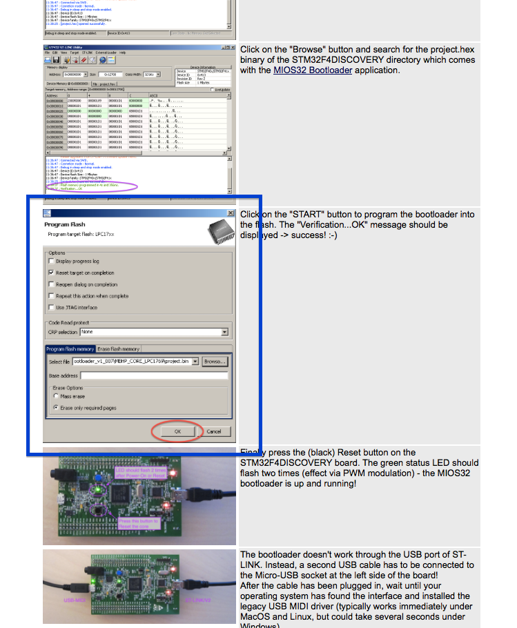
There is a wrong Picture in the Manual how to Load the Bootloader of STM32F4.
This is from LPC17:
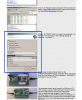
This is the right one:
best regards
novski
-
yes. found it. thanks for your patience...
for future, this is the correct syntax:
RESET_HW LCD â€%C†LCD â€@(1:1:1)OLED1†# Test D-OUT LEDmatrix board DOUT_MATRIX n=1 rows=8 inverted=1 sr_dout_sel1=1 sr_dout_r1=2 sr_dout_r2=3 # Matrix control by a Encoder connected to DIN ENC n=1 sr=1 pins=0:1 type=detented2 EVENT_ENC id= 1 fwd_id=LED_MATRIX:1 type=CC chn= 1 cc= 24 lcd_pos=1:1:2 label=“^std_enc†LED_MATRIX_PATTERN=1 LED_MATRIX_PATTERN n= 1 pos= 0 pattern=0000000000000000 LED_MATRIX_PATTERN n= 1 pos= 1 pattern=1000000000000000 LED_MATRIX_PATTERN n= 1 pos= 2 pattern=1100000000000000 LED_MATRIX_PATTERN n= 1 pos= 3 pattern=1110000000000000 LED_MATRIX_PATTERN n= 1 pos= 4 pattern=1111000000000000 LED_MATRIX_PATTERN n= 1 pos= 5 pattern=1111100000000000 LED_MATRIX_PATTERN n= 1 pos= 6 pattern=1111110000000000 LED_MATRIX_PATTERN n= 1 pos= 7 pattern=1111111000000000 LED_MATRIX_PATTERN n= 1 pos= M pattern=1111111100000000 LED_MATRIX_PATTERN n= 1 pos= 8 pattern=1111111110000000 LED_MATRIX_PATTERN n= 1 pos= 9 pattern=1111111111000000 LED_MATRIX_PATTERN n= 1 pos=10 pattern=1111111111100000 LED_MATRIX_PATTERN n= 1 pos=11 pattern=1111111111110000 LED_MATRIX_PATTERN n= 1 pos=12 pattern=1111111111111000 LED_MATRIX_PATTERN n= 1 pos=13 pattern=1111111111111100 LED_MATRIX_PATTERN n= 1 pos=14 pattern=1111111111111110 LED_MATRIX_PATTERN n= 1 pos=15 pattern=1111111111111111
-
im using a LPC1769 since my STM32F4Disco turned out to be the smal brother... :pinch: (its on the way to you now...)
I havent changed or Deleted the Files since a long time so the .NGR was never touched and is empty.
-> i just had to notice that there is a warning and it reports that there is no LED.NGR file.
[117358.626] [MBNG_FILE_C:8] WARNING: unsupported parameter in DOUT_MATRIX n=1 ... sr_dout_row=1
[117358.666] [MBNG_FILE_C] Event Pool Number of Items: 1
[117358.666] [MBNG_FILE_C] Event Pool Allocation: 41 of 24576 bytes (0%)
[117358.666] Patch 'LED' loaded from SD Card!
[117358.678] [MBNG_FILE_R] /LED.NGR (optional run script) not found
-
Hi
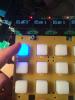
Today i tried a new part of my Fadercore, its a Matrix of 8 rows and 16 LEDs. Purposed to be a LED Level-Meter.
To test, i connected just one Row and 16LEDs and hocked a Encoder to a DIN board. So by turning the Encoder i get a Value from 0 to 127.
Then i wanted to make a simple Test like it wold be LEDs around the Encoder. But somehow again, i don't understand why my code doesn't work.
This is my .NGC file:
RESET_HW

LCD "%C"
LCD "@(1:1:1)OLED1"

# Test D-OUT LEDmatrix board

DOUT_MATRIX n=1  rows=8  mirrored_row=0 inverted_sel=0 sr_dout_row=1 sr_dout_sel1=2  sr_dout_sel2=3

# Matrix control by a Encoder connected to DIN
ENC n=1 sr=1 pins=0:1 type=detented2

EVENT_ENC id= 1  fwd_id=LED_MATRIX:1   type=CC chn= 1 cc= 24  lcd_pos=1:1:2 label="^std_enc" LED_MATRIX_PATTERN=1

LED_MATRIX_PATTERN n= 1  pos= 0  pattern=0000000000000000
LED_MATRIX_PATTERN n= 1  pos= 1  pattern=1000000000000000
LED_MATRIX_PATTERN n= 1  pos= 2  pattern=1100000000000000
LED_MATRIX_PATTERN n= 1  pos= 3  pattern=1110000000000000
LED_MATRIX_PATTERN n= 1  pos= 4  pattern=1111000000000000
LED_MATRIX_PATTERN n= 1  pos= 5  pattern=1111100000000000
LED_MATRIX_PATTERN n= 1  pos= 6  pattern=1111110000000000
LED_MATRIX_PATTERN n= 1  pos= 7  pattern=1111111000000000
LED_MATRIX_PATTERN n= 1  pos= M  pattern=1111111100010000
LED_MATRIX_PATTERN n= 1  pos= 8  pattern=1111111110000000
LED_MATRIX_PATTERN n= 1  pos= 9  pattern=1111111111000000
LED_MATRIX_PATTERN n= 1  pos=10  pattern=1111111111100000
LED_MATRIX_PATTERN n= 1  pos=11  pattern=1111111111110000
LED_MATRIX_PATTERN n= 1  pos=12  pattern=1111111111111000
LED_MATRIX_PATTERN n= 1  pos=13  pattern=1111111111111100
LED_MATRIX_PATTERN n= 1  pos=14  pattern=1111111111111110
LED_MATRIX_PATTERN n= 1  pos=15  pattern=1111111111111111
I see the Value rising but the LEDs are always ON. Also if i turn "inverted_sel=1"
What am i doing wrong?
best regards
novski
-
The tiny line on the end of my script was evil to me today...
EVENT_LED hw_id=1
Made that when pressing a single button in the first row then all LEDs in that column went on.
You might think its not possible, but it took me a day to realize that... :sad:
Well the wether was not good at all, so didn't miss anything.
best regards, novski
-
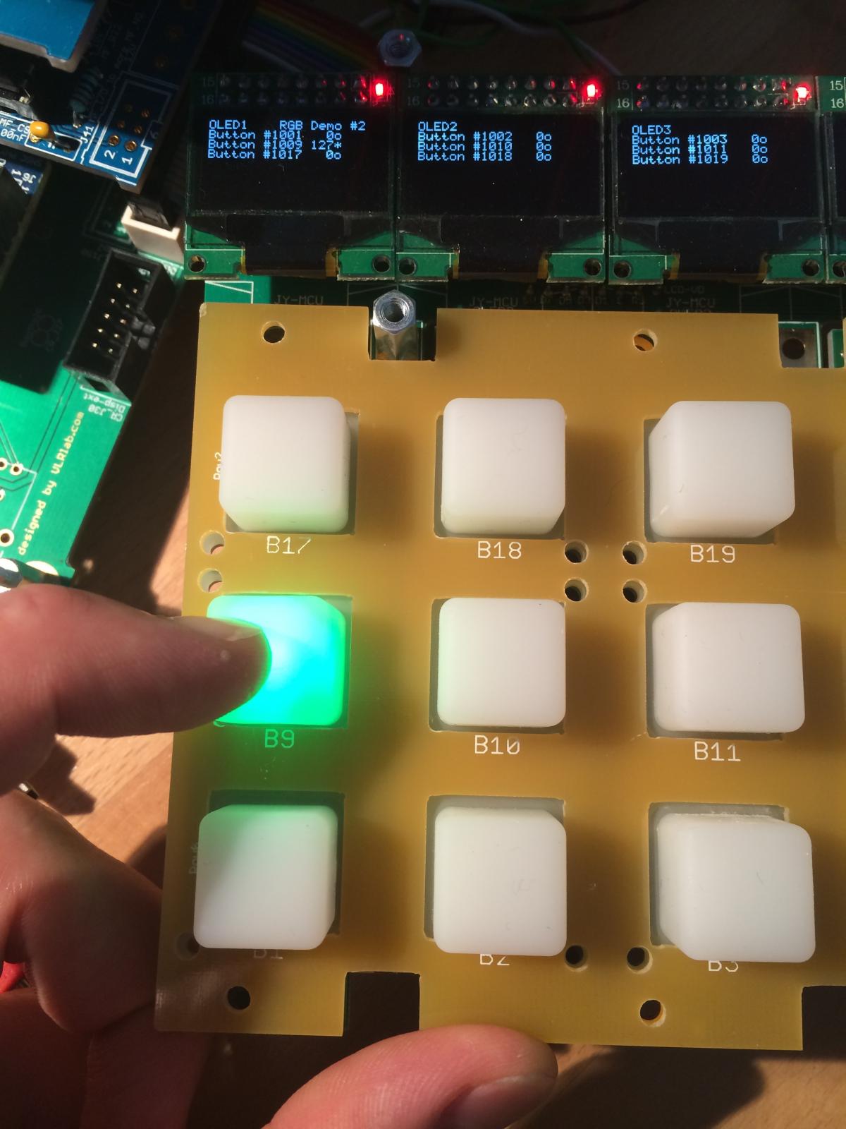
Why does this work
RESET_HW

LCD "%C"
LCD "@(1:1:1)OLED1"
LCD "@(2:1:1)OLED2"
LCD "@(3:1:1)OLED3"
LCD "@(4:1:1)OLED4"
LCD "@(5:1:1)OLED5"
LCD "@(6:1:1)OLED6"
LCD "@(7:1:1)OLED7"
LCD "@(8:1:1)OLED8"

# In this demo we configure individual brightness levels for the LEDs from EVENT_BUTTON events

LCD "@(1:10:1)RGB Demo #2"

DIN_MATRIX  n=1  rows=4  sr_dout_sel1=1  sr_din1=1                     button_emu_id_offset=1001
DOUT_MATRIX n=1  rows=4  sr_dout_r1=2    sr_dout_g1=3 sr_dout_b1=4     led_emu_id_offset=1025

# These button functions forward their value also to LEDs
# it's possible to set the rgb levels in the button event, it will be forwarded as well!

EVENT_BUTTON  id=1001  fwd_id=LED:1025  type=NoteOn key=36 chn=1  rgb=15:0:0 lcd_pos=1:1:2 label="^std_btn"
EVENT_BUTTON  id=1002  fwd_id=LED:1026  type=NoteOn key=37 chn=1  rgb=15:0:0 lcd_pos=2:1:2 label="^std_btn"
EVENT_BUTTON  id=1003  fwd_id=LED:1027  type=NoteOn key=38 chn=1  rgb=15:0:0 lcd_pos=3:1:2 label="^std_btn"
EVENT_BUTTON  id=1004  fwd_id=LED:1028  type=NoteOn key=39 chn=1  rgb=15:0:0 lcd_pos=4:1:2 label="^std_btn"
EVENT_BUTTON  id=1005  fwd_id=LED:1029  type=NoteOn key=40 chn=1  rgb=15:0:0 lcd_pos=5:1:2 label="^std_btn"
EVENT_BUTTON  id=1006  fwd_id=LED:1030  type=NoteOn key=41 chn=1  rgb=15:0:0 lcd_pos=6:1:2 label="^std_btn"
EVENT_BUTTON  id=1007  fwd_id=LED:1031  type=NoteOn key=42 chn=1  rgb=15:0:0 lcd_pos=7:1:2 label="^std_btn"
EVENT_BUTTON  id=1008  fwd_id=LED:1032  type=NoteOn key=43 chn=1  rgb=15:0:0 lcd_pos=8:1:2 label="^std_btn"

EVENT_BUTTON  id=1009  fwd_id=LED:1033  type=NoteOn key=52 chn=1  rgb=0:15:0 lcd_pos=1:1:3 label="^std_btn"
EVENT_BUTTON  id=1010  fwd_id=LED:1034  type=NoteOn key=53 chn=1  rgb=0:15:0 lcd_pos=2:1:3 label="^std_btn"
EVENT_BUTTON  id=1011  fwd_id=LED:1035  type=NoteOn key=54 chn=1  rgb=0:15:0 lcd_pos=3:1:3 label="^std_btn"
EVENT_BUTTON  id=1012  fwd_id=LED:1036  type=NoteOn key=55 chn=1  rgb=0:15:0 lcd_pos=4:1:3 label="^std_btn"
EVENT_BUTTON  id=1013  fwd_id=LED:1037  type=NoteOn key=56 chn=1  rgb=0:15:0 lcd_pos=5:1:3 label="^std_btn"
EVENT_BUTTON  id=1014  fwd_id=LED:1038  type=NoteOn key=57 chn=1  rgb=0:15:0 lcd_pos=6:1:3 label="^std_btn"
EVENT_BUTTON  id=1015  fwd_id=LED:1039  type=NoteOn key=58 chn=1  rgb=0:15:0 lcd_pos=7:1:3 label="^std_btn"
EVENT_BUTTON  id=1016  fwd_id=LED:1040  type=NoteOn key=59 chn=1  rgb=0:15:0 lcd_pos=8:1:3 label="^std_btn"

EVENT_BUTTON  id=1017  fwd_id=LED:1041  type=NoteOn key=68 chn=1  rgb=0:0:15 lcd_pos=1:1:4 label="^std_btn"
EVENT_BUTTON  id=1018  fwd_id=LED:1042  type=NoteOn key=69 chn=1  rgb=0:0:15 lcd_pos=2:1:4 label="^std_btn"
EVENT_BUTTON  id=1019  fwd_id=LED:1043  type=NoteOn key=70 chn=1  rgb=0:0:15 lcd_pos=3:1:4 label="^std_btn"
EVENT_BUTTON  id=1020  fwd_id=LED:1044  type=NoteOn key=71 chn=1  rgb=0:0:15 lcd_pos=4:1:4 label="^std_btn"
EVENT_BUTTON  id=1021  fwd_id=LED:1045  type=NoteOn key=72 chn=1  rgb=0:0:15 lcd_pos=5:1:4 label="^std_btn"
EVENT_BUTTON  id=1022  fwd_id=LED:1046  type=NoteOn key=73 chn=1  rgb=0:0:15 lcd_pos=6:1:4 label="^std_btn"
EVENT_BUTTON  id=1023  fwd_id=LED:1047  type=NoteOn key=74 chn=1  rgb=0:0:15 lcd_pos=7:1:4 label="^std_btn"
EVENT_BUTTON  id=1024  fwd_id=LED:1048  type=NoteOn key=75 chn=1  rgb=0:0:15 lcd_pos=8:1:4 label="^std_btn"
but as soon as i have this:
EVENT_BUTTON  id=1024  fwd_id=LED:1048  type=NoteOn key=75 chn=1  rgb=0:0:15 lcd_pos=8:1:4 label="^std_btn"

EVENT_LED     hw_id=1
At the bottom of my .NGC it sets every Value in the Collum to 127.
Now it works. :rofl:
Wow. im so glad i found that...
It took me an entire day!
-
Hi TK.
Thanks for your reply
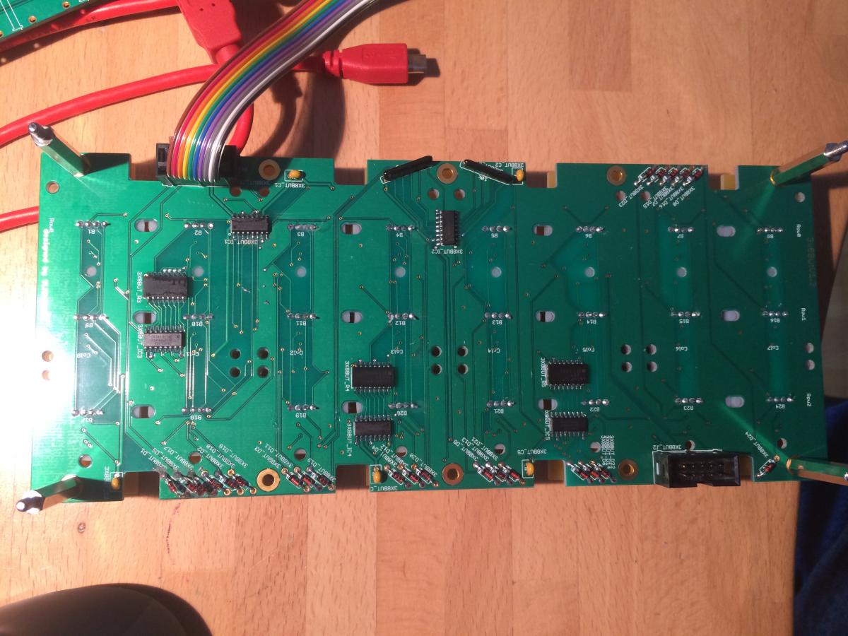
I can't swap anything because of the rubber buttons i made all in surface mount on the Bottomside of the PCB...

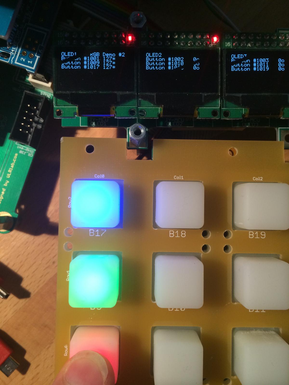
To me it looks like the column are short but if i measure B1 to B9 its a open line in both sides. also if i push the button B1 while i measure, B1 and B9 are not short connected...
I changed both SR 1&2 but it stays the same. If i press B1 the Value of B1,9,17 goes to Value 127 and all three LEDs lit up. as they should but if they get V127 but i don't know from where they get the V127 because im pressing just B1.


no clue.
i need a beer. :mad:

ALPS Motorfader from Yamaha Console
in Parts Questions
Posted
Hi
I ordered a box of those Faders new and have the ones i didn't use now for sale one my store.
Its a RSA0N11M9A0J
It should have a Resistance of 10k. I don't understand why you measure 14k.
I made some marks on the picture...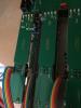
best regards
novski