
Scifo
-
Posts
68 -
Joined
-
Last visited
-
Days Won
1
Content Type
Profiles
Forums
Blogs
Gallery
Posts posted by Scifo
-
-
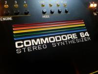
Hey guys!It's ready!Stuffed with two 6581s, and also has the option to use 8580s, hence the "SID 6581/8580" on the panel. The 6581/8580 filter caps have sockets for easy replacing. I'm very happy with how the panel turned out, using the old C64 rainbow logo.I decided from the beginning to exclude the matrix, since I haven't really used it on the first MB we built. It turned out to be a lucky decision, because when we were about to install the OLED display, it was too much sunk into the panel,leaving an ugly gap between the display and the panel. So dad moved the OLED to the "matrix-area" and changed the connections, so the OLED display is now really nicely lined up along the panel. I also wanted to the have the display tactile switches on the left side of the display, because I always use my left hand on the box, so when I press those switches, my hand is not blocking the view of the display, which would be the case if they were on the right side.Again, me and dad would like to thank TK & Co. for all the help. Could never have built this without your help.Sound demo:Some pics:
-
 1
1
-
-
Hey TK, thanx for the reply.
That SHIFT-thing sounds like a good solution. First I thought that holding down SHIFT would make the 1-15 value knobs go too fast, but I noticed they are not affected by holding SHIFT. Only the "long" values (0-255 etc) are affected by SHIFT. This is great news, so I will definitely try to edit that .inc-file and build a HEX-file so the MB will have the SHIFT activated by default. I let you know if I need any help doing that.
Thanks again.
Scifo
-
-
Hey guys!
Situation: I have the CUTOFF filter completely closed. To open it fully I need to turn MANY laps on the CUTOFF filter encoder to reach the max value. I suppose this is normal, since holding down SHIFT while turning the knobs increases the rate significantly. BUT, I'm playing at the same time so I have only one hand free.
My questions: Is there a hex-file or such I can edit so the dent-to-value-amount increases? So I can open the filter on that amazing bass to the max with 1 lap instead of 9.I tried looking for this before I posted, cause I have a feeling I've read somewhere that you can edit a file to change this, but I couldn't find any info.
Thanks in advance for your help.
/Scifo
-
We're almost done with the MB 6582, but ran into a problem.
Tactile switches marked 1 and 2 (check the attached photo) are not working (no changes on the display when pushing them and the belonging LEDs don't lit up). Everything else on the board is working. The rest of the tactiles, the encoders, the LEDs, the OS - everything is working except these two tactiles. Since we decided that we won't build a matrix on this one, we've excluded all the components inside the green lines (corner of the board). No LEDs, no tactiles, no matrix - nothing.
Will this affect the tactile switches marked 1 and 2 (tactiles at Oscillator WAVEFORM and OSCILLATOR).
EDIT: SOLVED!
-
Guten Abend Torsten!You are the King, I must say. I am Scifo´s father and I am using his password to write to you. Me (living in Sweden) and my son (in Finland) have been working together on two MB-6582 projects. (Skype is a great thing)The first project went very smooth due to all the fantastic information from all of you guys in the forum; Hawkeye, Wilba and others.I have been into the tube amp business for many years, but this is a totally unknown field for me. Soldering and follow schematics - no problem. But in this digital world I am lost.My son wanted a OLED display in his box but we went into a problem. We spent hours, no, days, trying to solve the problem. 8-bit, 4-bit, 8-bit again and back to 4-bit...Today we got your message and resoldered pics, pins and loaded the LCD-file. WOW, what a nice display!Thank you so much for your assistance. Again - you are the King.Best regards,Björn
-
The Vintage sysex bank is installed and encoders/tactiles are all working, but we have an issue with the OLED display. We don't have any text on it what so ever.
The model we have is from Electronic Assembly, model nr EA W204-XLG.
Datasheet here http://www.lcd-module.com/fileadmin/eng/pdf/doma/olede.pdf
Please don't tell me we've wasted our money... :no:
-
The problem written above was solved after we installed all the ICs, the PIC and the two SIDs. I guess some of these components "helps" the caps to drain (?).
Anyhow, problem solved.
The hex-file has been installed and we hear a nice boot-up jingle.Now we go on to finish off the control surface. We found an LCD with black background and yellow text - just like I wanted. Crystalfontz has one just like that, but we managed to find a company in Sweden who sold the same.
We did the PSU Option B, so we can change between 9v and 12v with a jumper, and the filter caps are not soldered - they are installed in a socket, so changing will be easy.
-
Things are moving forward! Now we hit the first bump on the road.
When I turn on the power switch, all voltages are OK, but when I turn off and on again quick there are no voltage at all. Off again and wait approx 30-60 seconds, everything is OK.
It seems that the electrolytic capacitors need to drain between on and off.
Anybody had this problem? Thanks in advance.
-
I would like to make the front panel as small as possible, so I want to leave out the matrix LEDs. Are there any complications by doing so?
-
Hey guys, I came here through a simple Google search of the serial number on a 6581 chip in my computer.
It's the 6581 5084 Korea AH395568 2.
Could there be more chips with this exact number, or is this the same chip you, toadstool, was selling?
Just curious.
-
So we've decided to use SmashTV's base board and build the top board ourselves, to fit the breadbox front panel.
I like the front panel in this project http://www.subatomicglue.com/sidl0g/
The only difference is that I would like to completely skip the 8x8 matrix (I have it on my MB-6582 and I never seem to use it), and I'll use a 4-row LCD instead of a 2-row being used here.
-
It doesn't seem like SmashTV has a 2-SID-socket board, so I'm planning to order the 6582 boards, which I already know how to put together. The top board won't fit a C64-case front panel (i suppose), but we're thinking of actually cutting out the top board and place them where they need to be to fit the front panel.
We'll order the boards only - not the parts list since these can be found here in Scandinavia.
Would it be enough to order one preburned PIC since we're only going to use 2 SIDs?
-
Hi Thorsten, thanks for the quick reply. I'll definitely go with SmashTV, we were very satisfied with the 6582 boards he did. Can you (or anyone) tell me exactly what I need to order from him, so I don't miss out on something and have to place another order later? Thanks again! Robert
-
Hello again, Gentlemen.
It's time to build another synth. This time, me and Dad decided to go old-school and build a simple stereo-SID using two 6581's, inside a 64 breadbox case, using its old PSU as recommended.
My initial question is where to get the PCB's. For the MB6582, I orded the kit from SmashTV in USA, but since I live in Finland, I wonder if there's a place in Europe to order the 2-socket version. I found Mikes Elektronik in Germany, is that the place? Exactly what products do I order from him to get started?
Best regards
Robert
-
Yes - but then you know that already :phone:
:hyper:
-
It's finally done and working perfectly!
I took some pictures (not very good ones), and composed a multi-track demo using only MB-6582 sounds.
I would like to thank the following people:
TK, Hawkeye, NorthernLightX, rosch, ilmenator, jojjelito, kristal=, Antix, Altitude and Johey.
You guys have a great community here and it's an honour to be part of it.
Best regards
Robert Engstrand (Scifo)
Helsinki, Finland
-
YES! All encoders are working and the MB 6582 is COMPLETED, and sounds FANTASTIC!
-
My Dad was confused when he skipped the GND connection between the base board and the CS, reading somewhere that it's "not necessary".
I took a close-up picture on the headers, just so you guys know how it looks like there.
Please tell me that at least one of these headers need to be connected to the CS for the encoders to work.
-
Dad sent the MB6582 to me. The setup8580 hex file is still not working for me (Dad had the exact same result), but when I load in the v2_vintage sysex, everything seems to work except the encoders. Same thing with the setup_tk2 hex file - works perfect.
All LEDs are working, all tactile switches are working, the synth sounds perfect, I can edit the sounds (with the use of the switches) etc, but not a single encoder is working.
I found another thread here
which sounds pretty much like the same problem I have.
Wilba's answer tells something about that the ground connection to the CS PCB might be broken.
(We're just at the finish line now, I just need to crawl the last damn meter :fear: )
Any thoughts, TK, or others out there?
-
Are you using identical SIDs?
We ran the testtone-application without the SIDs. Socket tone only, cause we've already confirmed that both SID chips are working.
Did your father get any error messages during the upload?No.
Can't be excluded.Another upload could help.
But consider, that a previously incomplete upload could lead to a wrongly initialized patches into the BankSticks - and this could explain, why some SIDs are not working (e.g. because parameters of the left side SID are corrupted).
This could be solved by uploading the preset library.
Exactly what file is the preset library? Don't find any in the download section.
MB6582 uses a button/LED matrix configuration, therefore MIDIO128 (V2) can't be used for testing.There are no debug instructions for this.
Ok. Let's hope the preset library will fix this issue.
Another thing: There's a trimpot under each 4 PICs and one a bit lower to the right. When we turn the pot under PIC1 (master core), it adjusts the LCD contrast. And, what are the other 4 trimpots for?
Thanks, TK!
Best regards
Scifo
-
Thank you, TK, for the answer.
1. We ran the mbsid_testtone and there is a tone coming from all 8 sockets, 3 of which produces a somewhat lower volume, but still a tone. Is it very strange that some sockets produce different db?
2. About the mbsid_interconnection_test_v2:
Starting the test, it says you need to connect the multimeter to pin A0. Where exactly is this pin? Should the test be done with or without the SID-chips, or doesn't it matter?
EDIT: Managed to complete the test. All pins, on all 8 sockets, are OK.
3. When booting up the synth after the 8580 setup-hex file has been loaded into all 4 cores, only 3 LEDs shine up and some of the SELECT buttons are not working.
My gut feeling says that all hardware is working (or at least correctly assembled), and that something is not correct with the software. COULD it be that the USB MIDI interface haven't been able to completely transferred the hex-file to the synth correctly? That there are some parts on the software missing, hence some of the LED's and buttons are not working. Or is that an impossibility, cause the synth won't even start up if the hex-file hasn't been received 100% ?
4. To test the buttons/encoders, should we use the MIDIO128 for this? Are there any instructions on how to use this program?
5. Which SID-socket is the boot-up arpeggio played from (just curious)?
Best regards
/Scifo
-
UPDATE 2: As I've mentioned earlier, we have sound coming from the synth, so we know at least that one of the SID-chips were working. We removed both and tested with only one chip in SID 1A (the rightmost socket when facing the midibox), and there was NO sound. Moved the chip to 1B (second rightmost), and there we have sound. Tried with the other chip - same result. So both chips are working, but I'm worried that the SID-socket 1A is faulty.
-
UPDATE: We found Wilba's matrix LED-test in an old topic and managed to upload the test-hex-file and ALL LEDs are working! :phone:
But why on earth are only 3 LEDs lighting up on boot-up? :pinch:
Alpha Encoders – are they cheap rubbish? (MB6582)
in MIDIbox SID
Posted
I have issues with my Alpha encoders that I bought from Mouser. For example, if I turn CUTOFF clockwise going from 000 towards 255, it sometimes jumps a few steps counter-clockwise randomly now and then along the way, which is extremely annoying. If I turn the knob really slow, I don't have this problem. If it's the encoders fault or a solder/building issue, I cannot tell.