

esher
-
Posts
48 -
Joined
-
Last visited
-
Days Won
2
Content Type
Profiles
Forums
Blogs
Gallery
Posts posted by esher
-
-
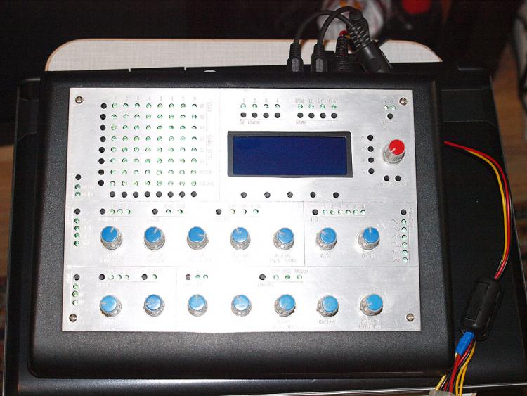
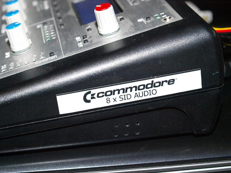
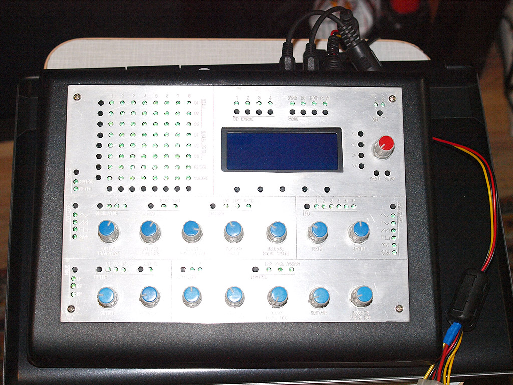
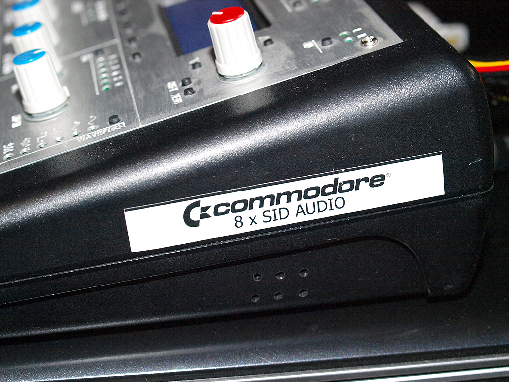
There is MB6582 here. Update: sold, so nevermind.
-
SOLD
Hi all. There is MB6582 for sale. Was built in 2014, and then was powered only 10-20 times i think. Too much for me listening SID files and not using all the power of the synth.
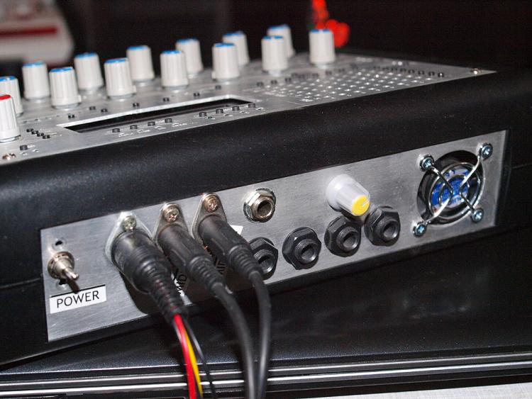
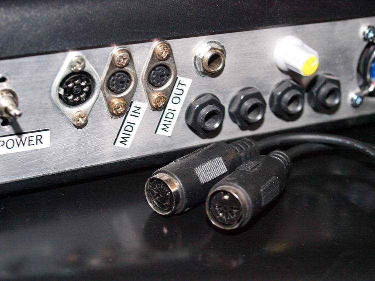
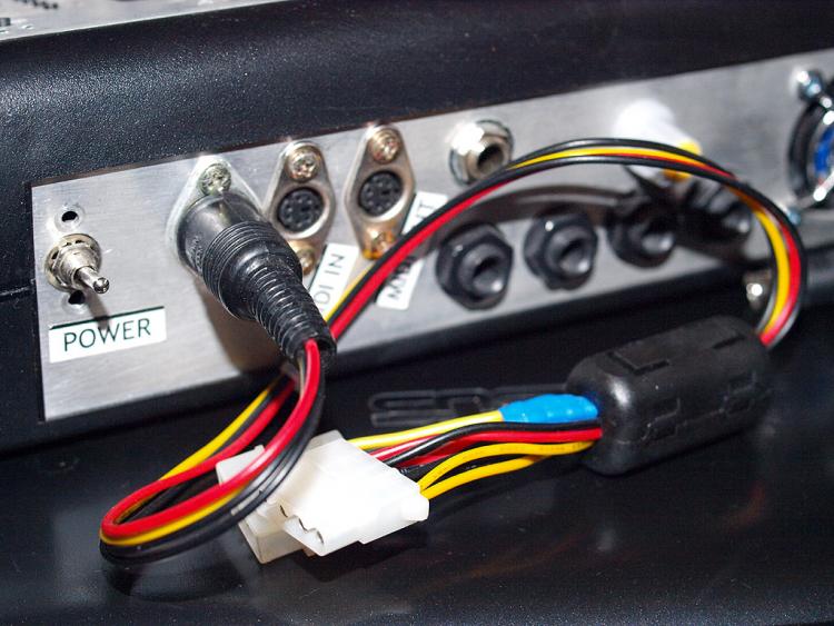
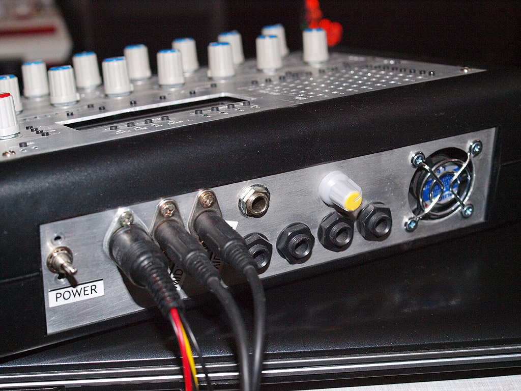
Back panel is not standard as it was problems to find the power switch and MIDI sockets, so i used mini DIN sockets with Creative Labs adapters from old Audigy 2 ZS Platinum.
Also there is no power adapter included, the power can be taken from PC power source or you just can use other 5+12v sources.
The synth has internal mini amplifier with small stereo speakers placed at left and right of the case.It can be completely switched off (yellow knob is the amp on/off switch with volume control).
All 8 SIDs are 8580, 4 of them have broken filters (2 working, 1 not),
don't know how to price them, your offers on this 4 are welcome. I bought them from china seller and was not able to test them in a deal protection period,it was too late when i tested them. I
have not calculated how much i spend on components, need few days to find the purchase history for most components, so i'll post the price later.Edit: according to payments history i spent 685 USD. This includes half-priced 4 SIDs with broken filters (bought from china seller for 120usd, priced to 60usd). Shipping (US and EU calculated) will cost 50 USD = total 735 USD.
Edit2: as i'm going to travel in september for 3 weeks, i'll give 60 usd discount to buyer before 1 september. That will be 675$ with shipping.
If you are interested to buy this unit, welcome to discussion or pm me.
-
I had the same problem time ago on MB6582 and as i remember this was about GND, aluminium back panel and MIDI sockets. Never catched it on my second SID device with plastic back panel.
-
It could be, that your programmer doesn't clear the ID bits - in this case, the wrong baudrate will be selected.
There is a workaround which is documented here: http://www.ucapps.de/howto_debug_midi.html
Search for "TEST SW2"
Best Regards, Thorsten.
Thanks a lot! After tens of tries to write this hex with G540, i did very simple 3-resistor serial programmer (jdm compatible), and then wrote bootloader with PICPgm. Very simple, fast, and with right ID's. Now all chips working fine.
-
After testing with these config bits (0006 0f13 0080 3fc0 3fe0 3f40), i had come to new strange thing.
The board on which i testing the 4685 chip, old 452 chip working fine, detected by MIOS Studio, MIOS uploading and screen telling me "ready". Ok.
But with 4685 i receive only "FF"s instead of "f0 00 00 7e 40 00 0f 00 00 f7".
there it is:
Any hint what's going on? I tried to change FOSC3-FOSC0 to HS w/o PLL, and in that case i catch on midi input another hex "C0 00 random hex"
-
Hi all, i've got strange chinese pic programmer (G540) which supports 4685 chip at last.
I can load hex and burn it, but sofware can't read chip configuration bits (or fuses) from hex (i doubt if they really exist in hex).
The line of fuses now looks (in hex):
0007 1F1F 8285 3FC0 3FE0 3F40
Without proper fuses i can't really start testing new board because i dont know if the chip programmed correctly or not.
Any help?
edit: i found screenshot which shows me configuration bits but i have 2 bytes less than on my config windows:
0600 130F 8000 00B1 C03F E03F 403F

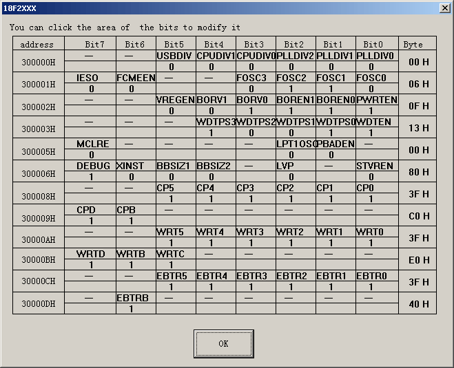
edit2: ok, i found that configuration on the screenshot is working.
-
Таки вышел на ÑвÑзь. ИнтереÑовалÑÑ Ñитуацией на почте, вÑвÑзи Ñ Ñитуацией в марте-апреле. Раньше не отвечал, Ñ‚.к. не был уверен что ответить (видимо, и обламывать не хотел). Ð’ общем ÑÐ¸Ñ‚ÑƒÐ°Ñ†Ð¸Ñ Ð² целом: оплата через веÑтернюнион, Ñ‚. к. не хочет терÑÑ‚ÑŒ деньги в Ñлучае пропажи поÑылки. У Ð¼ÐµÐ½Ñ ÐµÑ‰Ðµ ничего не пропадало, даже бандеролька одна благополучно пролежала в Ñтом 500 тонном заторе, как раз из СШÐ, и пришла ÑпуÑÑ‚Ñ 2 меÑÑца, так что надеюÑÑŒ и тут не пропадет.
-
 1
1
-
-
Ok, we've mailed. Thanks.
-
According to russian thread, some russian buyers were waiting for answer about 6 or 7 months, and some got no answer at all. Russian buyers are cursed here?
-
Ркакую печатку конкретно хотел приобреÑти ?
mb6582
В принципе, можно было бы и кучу mbhp и mbsid по цепочке, но больше заморочек.
-
То еÑÑ‚ÑŒ меÑÑц без ответа - Ñто еще нормально. Тоже напиÑал СмÑшТиВи, и фиг его знает, читает ли он вообще почту. Сам бы уже иÑпек платы за Ñто времÑ, были б файлы.
-
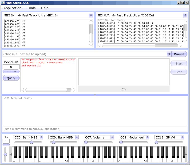
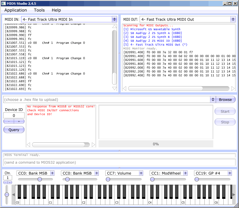
hello,
I am running into a similar problem. I have put bootloader on an STM32F4, the green led turns on as it should.
I Start MIOS Studio and select the IN (1) and OUT (2) port of the MIDI interface.
But i get a "No response From mios8 or mios32 core!"
Thanks in advance for your help
What MIDI interface are you using? I got similar problems with Audigy 2 ZS internal MIDI interface (with Midibox - no response at all; but with other devices it was working well, for example, with Roland SC and Yamaha MU series), semi-working Emu 2x2, but excellent results on FastTrack Ultra and ESI Juli@
-
Unsoldered, unstarted. I tried to contact SmashTV about shipping cost (to Russia) but got not answer.
So, may be there i will find the one who has unnecessary PCBs. PayPal available.
-
Hi all. I just soldered all the PCBs from Mike's shop, tested all DIN's and DOUT's, CORE - all is working fine.
But with MBSID v3 there is a problem with interconnection test.
During the test i only can get result for #CS pin which changes from 0 to +5v when appropriate key is pressed.
But no results from A0-A4 and D0-D7 #RES pins.
I thught it may be bad 74HC595, but installing new 595's was no effect at all.
Can it be PIC problem?
All cables and other PCB solderings was checked ten times - no errors.
All power pins shows the +12 and +5 where it must been.
Any idea?
edit: after testing separately 595's i found that all 595's are good and working with A0-A4 and #RES, but then in other place (connected to D0-D7) is not working, and when is placed - the first 595 is not working too.
edit2: accidentally, now is working all 595's. I think it was bad socket connection. Sometimes it need to be written about the problem, for kicking myself to solve the problem.


STM32F407_SID port?
in MIDIbox SID
Posted · Edited by esher
Hi, i am starting projecting custom stereoSID board based on STM32F4-disco dev layout (but no discovery board, only the mcu), since PICs are already outdated, can the PIC SID firmware be ported to STM32?
I am working at evenings in local company having access to Autotronik machine which can do all smd hardwork.
After the finish i will share the board if anyone want to build the same.
PS It's planned as mostly smd, besides SID and some hard-to-locate components. And may be i'll orient it as board for ArmSID or SwinSID only because then it will have 5v only power supply, thoughts?
edit: i didnot noticed i have sources for 2.044. I'll try to dig what's inside the code.