

fourfour
-
Posts
18 -
Joined
-
Last visited
Content Type
Profiles
Forums
Blogs
Gallery
Posts posted by fourfour
-
-
What hardware do you have attached to DIN?
[edit]
It looks as though you have a generic NGC. You'll need one that supports a particular protocol.
Here is an example of a config that provides support for mackie/logic control protocols: here
Hey Duggle.
I was thinking I needed something like this. Do I just replace my default NGC with this code?
-
Can you please post your configuration file: default.ngr from the core sdcard.
Here are all my files loaded on the SD.
-
Hey everyone.
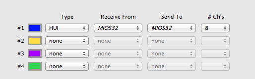
I am having trouble getting Pro Tools to respond to my controller. I have it setup in Pro Tools as HUI, but nothing seems to work.
Is there a setting I need to declare in MIOS for HUI Emulation? Or is that always available?
Setup:
LPC17
NG
DIN
Thanks!
-eric
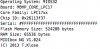
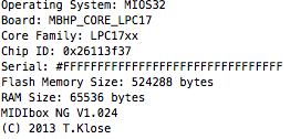
(the attachment shows the MIOS in italics, I just had it unplugged when I did the screenshot)
-
woot.
@novski that was it!
Again, thanks for the help everyone.
-
It all seems to be hooked up fine.
I just had some jumper wires laying around that I crimped some dsub connectors to. All those are passing current fine.
Do you have to #include a NGC file for it to load? Or does it load every file on the SD?
-
@duggle
Ok, I tested all the connections. The clk, data and RC all beep ok from the core to the first shift reg.
Thanks for your help.
-
@novski
I am following that 'first steps' tutorial
-
Hey Spirit.
Ya I get the voltage drop to 0V when the button is pressed.
I have this in HELLO.NGC
RESET_HWEVENT_BUTTON id=1 type=NoteOn key=36 -
I'm stuck again :/
I am new to hardware dev, I come form the software side of things. I appreciate everyones help getting me off the ground.
I have a DIN connected to J8 and a single button. I am trying to get the 'first steps' one button test to work. There is voltage and the button works.
Am I correct that the button gets wired to ground and D0? I get a voltage drop when the button is pressed, but nothing happens in MIOS.
Thanks!!
-
Ok! We have liftoff!
Thanks so much everyone.
-
@duggle: I assumed they just mirrored J8
e.g
Vs
Vd
Si
Sc
Rc
I have some ribbons on order. The site didn't state that I needed to order them separately.
Thanks for your help.
-
@spirit: oh my, thanks for catching that.
Unfortunately, that didn't solve the issue. LED still on all the time. I checked my wiring again over the whole board.
(how do you send a beer?)
-
Hey Duggle.
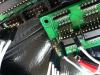
I am getting voltage to the DOUT board, tried using J8 and J9. Here are some pics, thanks for your help!!
-
Hey Pete.
Ya, I tried that already. I also tried setting individual pins to 0|1 and nothing happens.
-
Hey guys.
I feel super stupid atm. I can't get anything to work as expected. I need to get back the basics here.
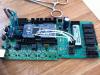
I am have the LPC17 and a DOUT connected via J8. I hooked up an LED to Vs and D7 and entered 'set dout all 0'. I am still getting 5v at D7 all the time.
Nothing else is connected.
What am I doing wrong? Board specs attached.
Thanks!!
-eric
-
Hey Thorsten!
Thanks for the quick response!
re: ProTools fader control
I am building a channel strip for a plugin. So all the encoders/buttons will control the plugin and the fader will be the output fader of the ProTools track. I need the fader to be controlled from ProTools and to control ProTools. The point would be to write and playback automation. I am not familiar with the protocols to know which would be best to implement.
I don't think MBNG would need any control.
Cheers.
-eric
-
Hey.
This is my first time posting and my first build. Thanks for all the hard work on this project. Very cool stuff!
I have a few questions on getting started. I have the LPC17 setup with the SD and working over USB.
My configuration is going to be:
- LPC17
- (2) DIN to control 21 Rotary knobs and 20 buttons
- (1) MF_NG to control 1 Motorized Fader (Alpha)
- (1) DOUT for LED
I won't be using any midi ports for this project, it will be USB-MIDI.
I have J4B of LPC17 connected to J11 of MF_NG. From here, I have no idea what to do to be honest. :smile:
I would love to make a detailed PDF of the connections to share. I will be interfacing this with ProTools and Reason, what is the best emulation for those?
Any help would be amazing.
Cheers.
-eric


Pro Tools - HUI Emulation
in MIDIbox NG
Posted
Where do I put this file? I am not familiar with how to use templates?
Thanks!