
Wapata
-
Posts
49 -
Joined
-
Last visited
-
Days Won
1
Content Type
Profiles
Forums
Blogs
Gallery
Posts posted by Wapata
-
-
In the general idea of Midibox_KB : should we use it only as an interface from the keyboard to midi, and then make a separate Midibox_NG project to take care of all the other things (like buton and led ) ? If so, what should be the connection between the two devices ?
-
Long story short : father in law did never talk again about the project. So I went to make a midification of my old Yamaha gear (Yamaha DSR-2000) but then the keyboard fall and is broken.
Now, we are a year later and i come back to midi keyboard. A 4 octaves one. And it's working ! And right now, i see some issue... like... The screen... it take me so much time to have it working and i did see that it's useless
! haha. And I can have 4 analog input, that's great, but not more than 4. And worst, i will never have "octave up/down" button because I can't have button.
So i should go to MidiBox_NG instead of MidiBox_KB, even for a simple nude keyboard. In fact, the only -really- missing things are the octave up/down, and being able to change the USB-Midi settings. Like I would like to have only two USB ports, one dedicated for the keyboard (with midi IN and OUT 1) and the other dedicated for Midi In and Out 2.
Well. Just to say : still alive !

-
2 hours ago, Hawkeye said:
as Windows seems to have quite buggy MIDI-USB.
Hi !
I dont say that as a excuse for Windows but : we have to keep in mind that before and after a firmware update, it is not the same USB device anymore. And MIOS don't let the old one go, and don't show the new one. But well, I think a patch to correct this specific usecase will never happen.
-
Thanks both of you for the complete answers !
Yes it will not be a complete DAW for sure, but you can put the song in your head quickly in, test some transposition and all and, after you had the big smile on your face that say "oh yeah that's it", export the result in MIDI to your computer and... Don't touch it for years because that's how computer-daw work.
What is a "BLM" ?
-
The link to the sources is... Intimidating.
In this page : http://www.ucapps.de/midibox_seq.html the PDF from Features / MIDI Remote functions (near the end) have no "Layer D" but two "Track 3".
No one see it since Midibox Seq V2

-
On 07/05/2018 at 11:22 PM, Hawkeye said:
* six polynote tracks linked to individual MIDI configurations
* six scenes, allowing for a total of 36 in-memory MIDI clips
Hi !
Can you tell a little more about that ? In the tracks, I choose my instruments so it's clear, but what about the scenes ? Is it the different parts of the song, Like intro - part one - refrain - part two - refrain - part three - break - refrain - end ?
Didn't you lost two scenes during the development, you talk about 8 scenes on YouTube I think ?
Thanks and have a great day (or night..) !
-
On 27/12/2018 at 9:40 PM, TK. said:
(need some time to think about the right connections)
Hi !
You can take this off your to-do list. The naked waiting keyboard hit the floor and have broken keys... So it is not my favorite keyboard anymore

-
Lol, it was too early in the discussion maybe
 Sorry
Sorry
-
Take a look:
There was no chance that I could find it with the search function but... By looking deeper and deeper in the forum I fall into this tread.
-
Yes ! Theses are good tips !
I'll try by myself now with standard connectors. I have to learn and it's a useful exercise. And with the files you provided it will help too. Thanks !
-
So... It take way too much time to start using eagle. What a nightmare for a such simple board:
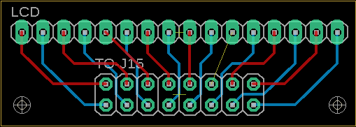
Note that i havent check the reverse/mirror pin thing yet because I have a question first: how to make the upper solder pads to touch the border of the board ? This way it will be possible to solder this board to a 90° angle to the LCD with no wire.
And then I will find how to add the ribbon connector schematic.. -
Hi ! I'm currently reading the Midibox NG manual. Is it helpful if I write some parts here that (in my opinion) could be changed ?
Like in this page: http://www.ucapps.de/midibox_ng_manual_fs.html
"Today we would prefer to use Fairlightiii's premade PCB solutioninstead - more informations about this once I get my hands on the PCBs! :-)"
As theses PCB will never be reedited, it is no more relevant ?
So. If comments like that is cool for you, I can continue. Or if it bother you, I can stop. But please note that by using my phone to read the doc and write on the forum, I have no way to format and use the code tool.
-
Hi !
I'm happy to say that the core is okay, i've soldered my second LCD and... it's working GREAT ! See the lasts pictures ;) https://photos.app.goo.gl/5bR4r2ivZe5dgYYW9
@TK. I've added three of them in the Gallery, please fell free to use them if you like.


-
 1
1
-
-
Happy to help !
-
Clear to me ! Thanks a lot !
Lesson learned : check, double check, triple check before power up !
-
1
-
-
Oh I see the triangle in the first photo ! I did miss a big I formation then, thank you ! Is there a page with ribbon tip and tricks ?
And sorry that I didn't understand you the first time. Language barrier maybe ;-)
-
33 minutes ago, latigid on said:
Because we normally connect displays on the rear side, the Core J15 is mirrored, so it's actually
 ________________________
|16 14 12 10 08 06 04 02 |
|15 13 11 09 07 05 03 01 |
__________----___________
It doesn't look true... Here is what happened when I clamped the ribbon (with V0 at pin number 04) :
 ________________________
|15 13 11 09 07 05 03 01 |
|16 14 12 10 08 06 04 02 |
__________----___________
And I can't mechanically change this order can I ? The red strip of my ribbon will always be clamped to the top right of this schematic (The last wire will alway be at the bottom left too).
The two opposite side of ribbon cable will alway be in diagonal, top right / bottom left as i understand. Did I miss something ?
-
7 minutes ago, Antichambre said:
I think all is reversed by pair!
Yes, this is what I think and write earlier. That the first reason why I'm in this particular sub-forum... There may be something really unclear about the "mirror" thing on the documentation page.
Just now, latigid on said:Could you check that these pin numbers correspond to those on the LCD when the cable is connected (with the power off)? Or are the pairs inverted as Bruno says?
The multimeter as show say "it doesn't". The V0 "bip" on the wire 4.
And yes it is like Hitachi
-
I'm back from the garage. It's -1°C ... cold. Anyway here is a google album with the pictures i have taken, just under the midi-notes attribution chart: https://photos.app.goo.gl/5bR4r2ivZe5dgYYW9
You can see where is the notch of the ribbon head, the big clear labels on the LCD PCB, the labels hidden under the "big black plastic of the ribbon port that hide" and finally, how I test and found where the V0 is.
Please not that I've tried to de-crimp the ribbon yesterday, but it was well crimped before the incident. -
It look MIOS8 compatible, not MIOS32. But the idea is cool. With 90° pin header the PCB + LCD + Cable will be "flatter" .
I have to reinstall eagle and sketch the idea ! Thanks !
-
I put the cable on the bottom and the soldering on the top. https://www.ebay.fr/itm/1602LCD-Blue-Yellow-HD44780-Character-Display-Module-5V-for-Arduino-Raspberry-Pi-/263750988179?varId=562961334972&txnId=2349798667016 but there is big labels.
I'll take some pictures tomorrow ;-)
-
Just now, Antichambre said:
sending core RS Pin to LCD V0 is worst,
Oh.. I think I did that, if wire 4 is V0, then wire 3 should be RS !
(Wire 1 and 2 swapped, 3 and 4 swapped, and so on)
-
Thank you both of you ! In fact I'm an old newbie here. My core was made in
2016(edit: the metadata of my pictures says October 2017), and I follow uCApps for more years than that ! Maybe 2004 (... Wow.. so long ?..).It's okay for me to broke an LCD, but the point here is about the indication on the website, they are confusing about the ports of the STM32F4. I mean... Really.
But on the other hand, I should have double checked the vcc and ground for sure.
-
Multimeter in "bip if wire" position. V0 is not in the wire 3 but the wire 4. Sorry I didn't check my messages before posting (baby things to do...) And forgot to mention it.
Yeah the pinout of the LCD is very clear and written on the PCB. The problem is one the other side, as I have the big black plastic of the ribbon port that hide all the important information written one the core PCB. Had to remove it to check... After the fire.
The LCD is probably dead (in French: le son (juste le son) d'un petit feu qui crépite est mauvais signe, la nouvelle odeur aussi, mais je testerais le nouveau câblage... Au cas où) but yes, I have an other one ! Lucky me...
88 keys piano midification
in MIDIfication
Posted
Yes I did see that. And I did know that NG cannot make the full range of velocity. That's why I keep KB for now.
Thanks for the answer !