2hb
-
Posts
18 -
Joined
-
Last visited
Content Type
Profiles
Forums
Blogs
Gallery
Everything posted by 2hb
-
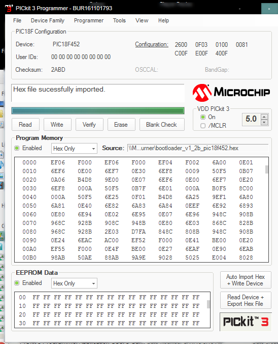
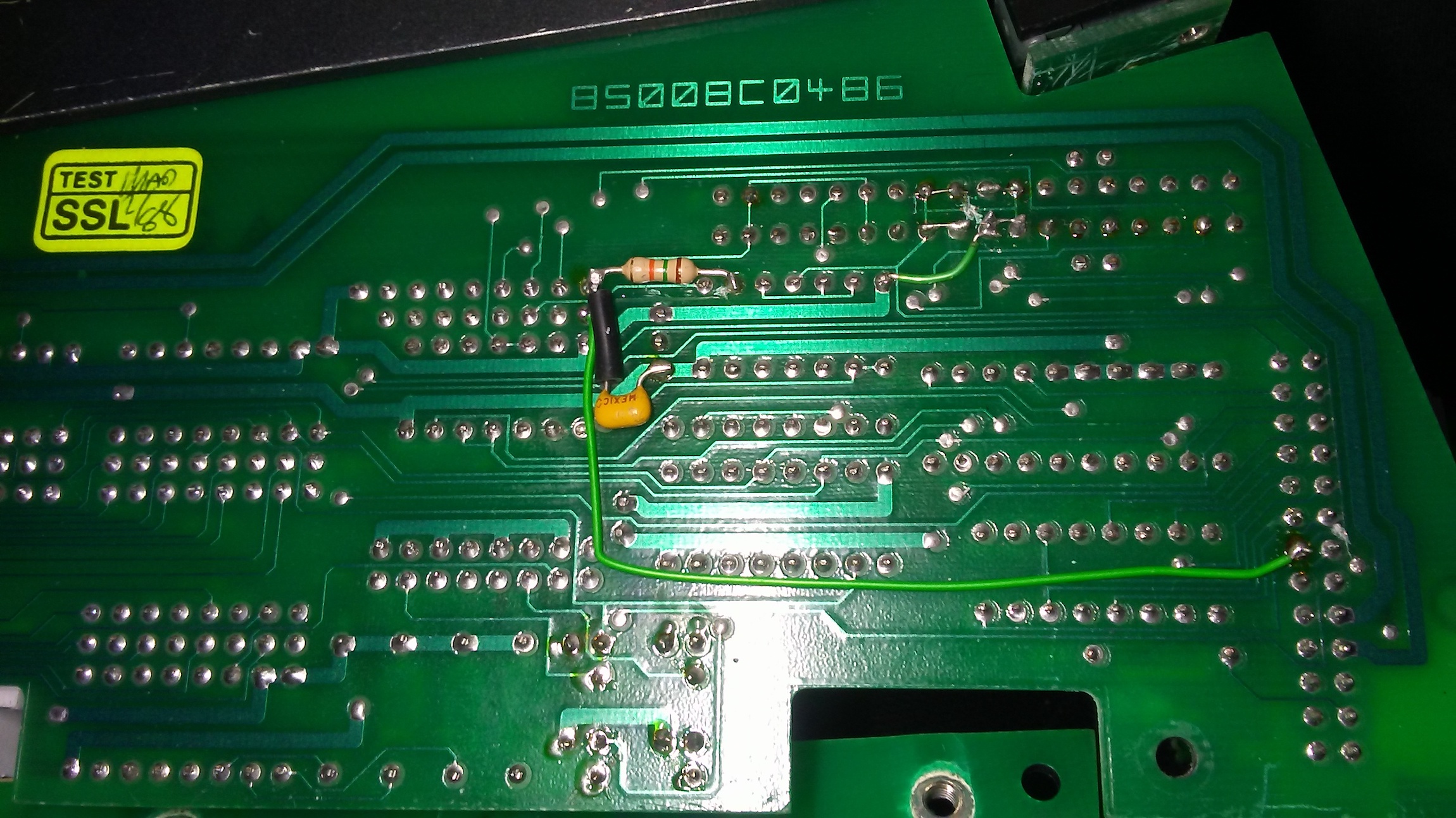
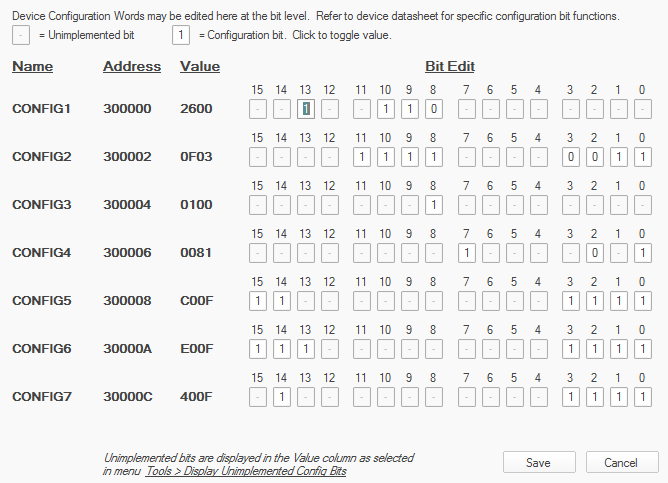
I know there are a lot of posts about this already, but I have gone through the troubleshooting guide and am still left with some confusion as to whether I am doing everything right. I am getting 5v everywhere on the mf_ng module. I've tried 3 different midi interfaces. a "usb uno" , presonus firestudio project, and rme raydat I have tried programming a pic18f452 and pic18f4523 using the pickit3 and the pickit3 software which is running in parallels. according to the the pickit3 software, the bootstrap upload has been successful, but I still can't connect to mios. When testing the grounds on the capacitors connected to the crystal i get 4.97v on one leg of either capacitor. I'm not sure if that is normal or not. But both capacitors get 5v on one leg. The crystal I am using is from Reichelt when I connect the pic into the socket on the module, I only get 3.23v on pin 14 of the pic, pin 12 is getting 4.97v (with the positive terminal of the multimeter connected to Vd of J2, and the negative terminal connected to the pic pins and capacitors) I've tried all the midi loopback tests and they have all been succesful 3.23v on pin 14 doesn't seem right to me. Maybe that is the problem? I'm not sure how to fix that though if it is I included some screenshots of the pic programming. The bit values are all default, do I need to change those at all?

-
They usually operate somewhere around 170volts so it is definitely something to be extremely cautious with. It is a separate high voltage power supply connected to the anode, the cathodes are all connected to the 74141 or K1551d1 like Antichambre said, the 74141 is connected to a 74HC595, a dout module ! I've never seen THX 1138, i should watch and try and spot them! For the coding, I would have to use the template for logic control for pro tools. I'm just not sure exactly how to forward the mtc digits to send on/off messages to the dout's outputs I've tried to forward the timecode values to a single led just as a test, but I don't know how to implement it properly. or if this is even the right direction. I tried from this section, which uses a sysex stream: But I'm not sure what to do.. I would think somehow forwarding the syxdump_pos to whatever the "led" outputs would be for the corresponding digit, if that makes sense. So for example, if syxdump_pos=:10:3, then forward what is needed to leds 1-4 (1=off, 2=off, 3=on, 4=on in this case for the digit "3" on the nixie tube) Would this be essentially what I would need to do? This section shows the cc values for direct access to the mtc digits within the logic control protocol:
-
I'm not sure I know how to answer, but it seems like the common method is to connect the nixie to a sn74141 or similar, with 4 connections ultimately, to the arduino. here is a diagram for what seems like the most simple way to do it from this page: http://www.instructables.com/id/How-to-Control-a-Nixie-Tube-with-an-Arduino/ the arduino sends basically a 4 digit binary value to the ic that corresponds for each number, 0 through 9, in the nixie. So I am thinking maybe, if it is possible to connect this to a dout module, that the mtc digits could somehow be programmed to send this 4 digit code instead of the 7 segment values. possibly with senders and receivers?
-
How would you go about setting up a nixie display for Midi timecode? I know there are drivers and boards available online for interfacing nixie tubes with arduinos. I am thinking if I used that to connect to a dout module, then maybe it would just be a matter of coding? Has anyone tried doing this?
-
Thank you!! It is all working now! I guess as a side note, do you think there could be a way to make the mutes not flash when you solo a channel?
-
I'm having trouble getting leds to work properly with pro tools At the moment I have the leds responding when I press solo in pro tools, but the problem is, when I press solo on any channel it will turn on all leds I have assigned. I know that the problem is in the way I'm coding because it is only doing this in pro tools. The code I am using is this, which are the cc equivalent values to sysex zone select/port on: EVENT_LED id= 1 type=cc chn=1 cc=12 range=0:0 EVENT_LED id= 1 type=cc chn=1 cc=44 range=67:67 I can't get them to respond with sysex messages, whereas it does work for buttons. For example, this was not working: EVENT_LED id= 1 type=sysex stream="0xb0 0x0c 0x00 0xb0 0x2c 0x43" I have the buttons configured in a similar way as shown before with cc messages with ranges and they work, so I thought maybe this could work for the leds, but it appears that is wrong What would be the right way to do this?
-
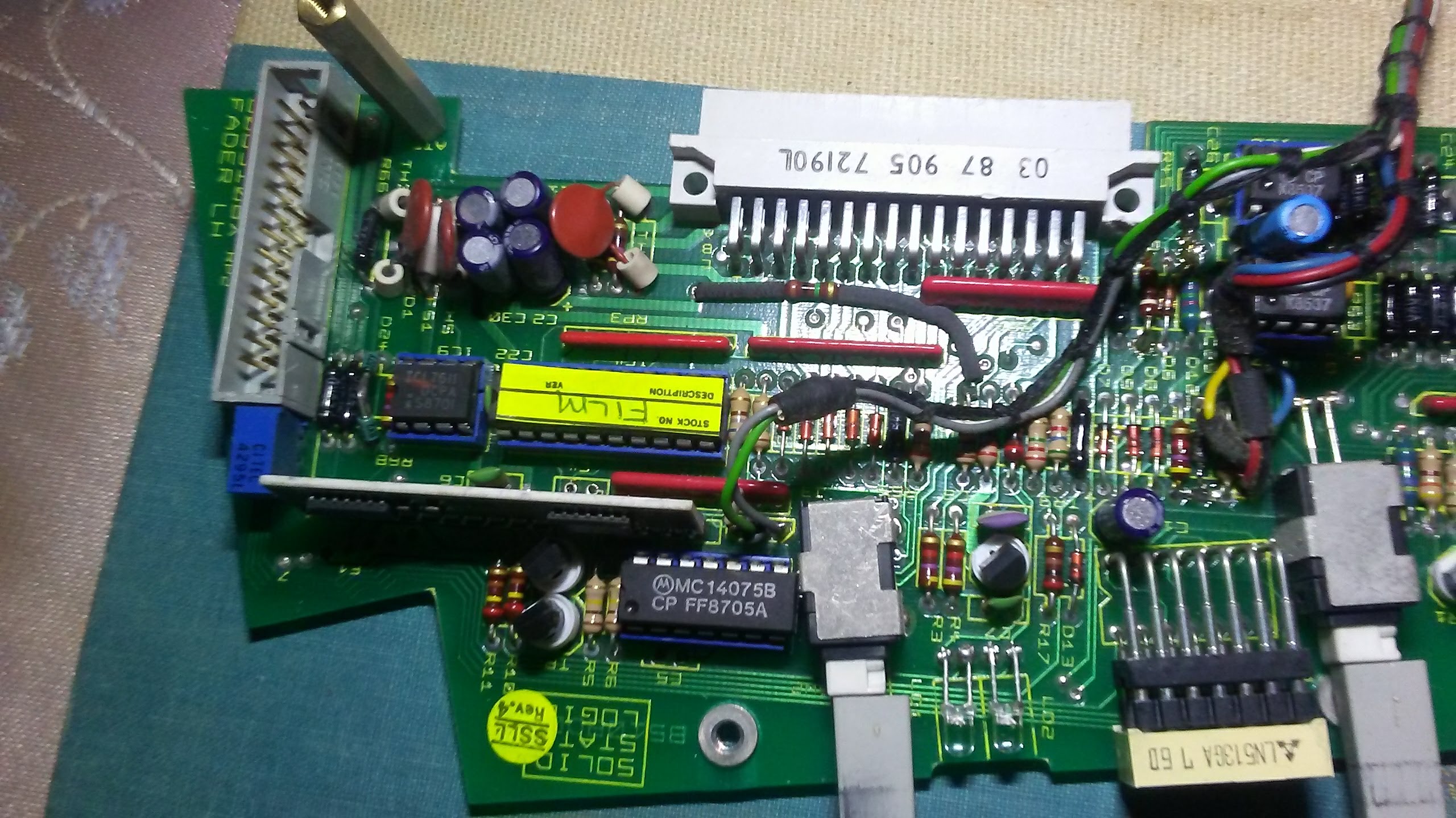
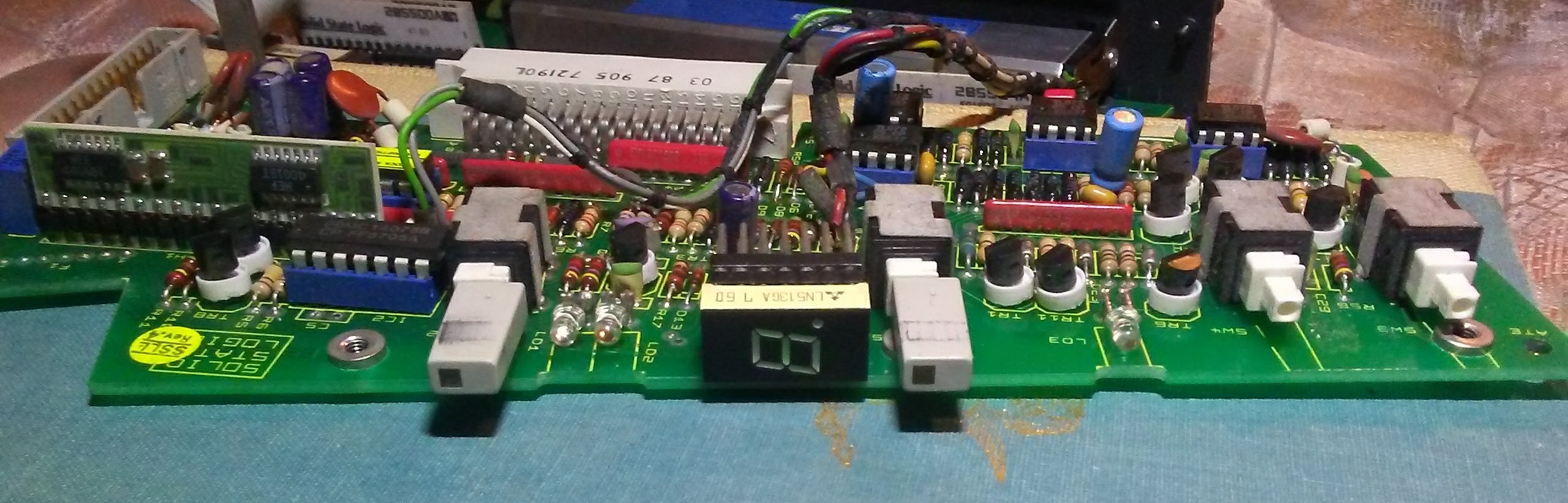
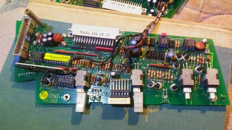
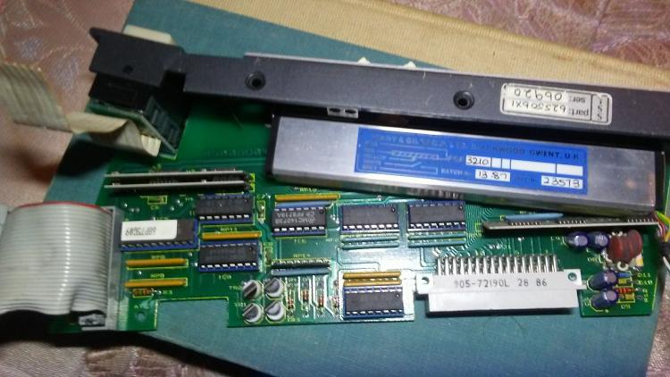
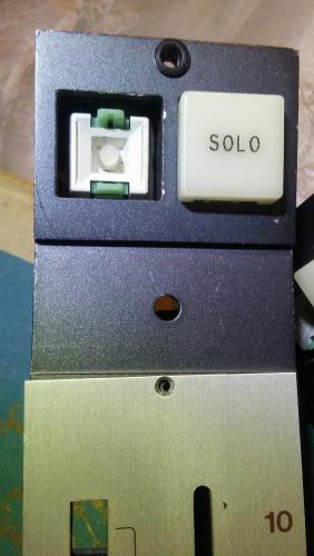
I'd be glad to share, there are two pcbs on either side, connected with a ribbon cable on top All of the modules I have are the same model sl506, but are all configured differently it seems, they all have these different mods on the outsides of the pcb On this one, the same "ic4" I posted earlier has a sticker with the word "Film" on it. They are from a 5000 series which i know were meant more for broadcast and post production. so maybe this was more formatted for film? Another interesting thing is the two extra buttons at the bottom. The sl506 doesn't have two bottom buttons on the front panel, but other 5k series faders do, so manufacturing-wise they didn't omit the switches based on the fader model, just the fader caps. There are even the leds inside, I know because I applied power to them and they lit up ! I'm guessing that later, they would make modifications by hand based on how the customer wanted their console configured, but it is all a mystery to me really Also sorry about the quality, I can try to take some better pictures, I just have the camera on my phone


-
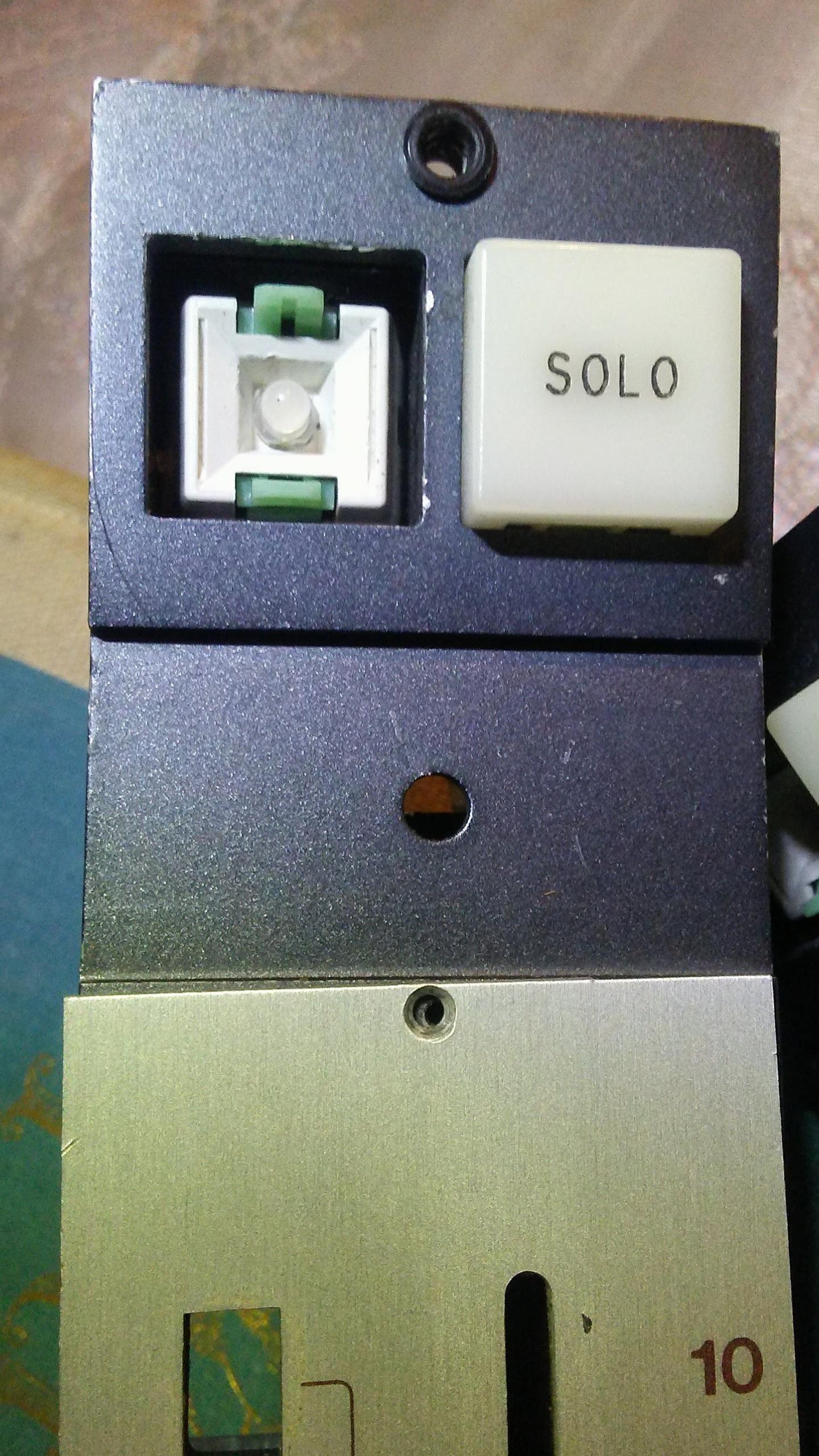
Hello! Yes exactly, eao switches, connected to a small pcb on the bottom, that is where i've been powering them, with the incandescents under the button cap That's what I meant to say, replace the incandescents with leds, i didn't know that was possible ! I feel silly now, I am very new to this sort of thing, I wasn't sure it would be so easy to interchange them They are just situated in a way inside the switch that seemed impossible to get out without a special tool, they are only 3mm, so t1 size? It is really hard to find t1 remover tools I tried using a precision flathead screwdriver to remove them and sure enough I broke some in the process, but I ended up just using a piece of electrical tape to remove all of them ! I just tested with a 3mm led in place, so now I just have to connect to a dout module. So I'll be using leds now with the dout as is. it's better that I keep things as simple as possible .. Thank you Zam! You help me once again And even though i'm not using the incandescents I still appreciate everyones help!! I very much appreciate this forum and midibox in general This is my first project so you'll probably be hearing more from me
-
here is a link to the manual for the fader module: https://mega.nz/#!8h1mgAaQ!TcjGyKONf1by4TnP1rBjYrE4w2c1744TLIW995_6qvw
-
I should be more clear on that, my idea was the latter, each fader module has a number of switches and leds, and in this case two incandescents, which were originally used for vca automation. I wasn't planning on powering the modules, I was thinking just to basically bypass the whole circuit and access the switches and lights directly to use solely as a controller. ep320pc-2 is the part number for that ic http://www.datasheets360.com/pdf/-3584855117084061587 The modules aren't really in the best shape, and I'm not sure if they are in complete working order (neither did the person I bought them from)
-
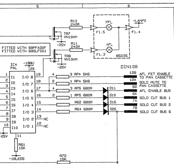
Okay, it was actually set for milliamps, so 14 mA not A, sorry for the misinformation! I am very new to this as you can probably tell The power supply i've been using is just a 12v adapter 1500mA output. I would just use leds, but there doesn't seem to be an easy way to remove them from where they are installed without breaking them, they are for the afl pfl switches from an ssl fader module ! .. There's not really much information about what the actual ratings are for them, but I did manage to find them in this block diagram from the manual (top right): Hopefully this provides a little more information on them. Thanks so much for the help!

-
I'm not sure if i did this right, but I connected the positive from the 12v power supply to the bulb via a multimeter, and the ground of the bulb connected to the negative of the power supply, it read about 14A, would that be the correct way to do it? I haven't ordered the dout module yet, so it would be the r5 version so would the vs and ground of the 2981 connect to the power supply's positive and ground through the two extra holes on the pcb where the arrays normally go? and then resistors would connect to the outputs 1-8 on the 2981?
-
Thank you, I appreciate the help, so a 2981 after the 595, are you saying it would fit where the resistor arrays would normally go? How would I supply the secondary voltage?
-
Hello, I was wondering if there was a way I could use a dout module to interface with incandescent bulbs that require more than 5v, I am not sure their exact voltage, somewhere around 12v. Would this be possible with an external power source somehow?
-
Hi Zam, Thank you so much! This makes a lot more sense, I have been trying to work off of the hui documentation to modify the template, but I didn't realize it uses CC messages, is there anything else I would need to change in logictrl.ngc other than the individual button events?
-
Hi everyone, I am very new to midibox, I have a DIN module connected to a stm32f4 core with logictrl.ngc loaded as the default patch. I am trying to get it to work in pro tools ultimately, but I havent been able to get it to work in logic either. I have a single button connected to D0 which mios is responding to, recieving this message [2095799.673] 90 18 7f Chn# 1 Note On C-0 Vel:127 but no response from pro tools. It's set up correctly in Peripherals (set for hui, mios in, mios out) I know there is probably something I am missing, but I'm having trouble finding anything specific to logictrl.ngc in the tutorials or the forum Any help is greatly appreciated! edit: it is working in logic, but still not in pro tools, the versions i have tried in are pro tools 10 and 11
-
Hi Zam! Thank you! I've been reading all your posts here about automating consoles, so its great to get a response from you! Ideally I would like it to pass audio, with mf914 or mf9101 faders, and maybe trying an rc filter for the noise, but I also know that makes things less accurate. This would all be just for a ramsa wr t820b. I really considered ordering your 89motion system, but it just seems way out of my league as far as building it, I am brand new to any kind of circuit building. I remember in your documentation you said there are dacs for every fader, is it an rc circuit you are using? Would it somehow work with midibox hardware? Thanks again!
-
I am brand new to midibox, I don't have any modules yet, as I am trying to figure out which ones to get exactly, I haven't found a sure answer to what I'm looking for specifically by looking in the forums and the general information on the ucapps site, maybe someone could help. I'm trying to make a controller for Pro Tools using 3 MF_NG modules , for 20 channels/faders total since it would be installed in an existing 20 channel console, but I'd also like to have buttons and leds for record enable, channel automation, as well as transport controls and automation selectors (read, write, latch, etc.) as well as leds for the record lights, which for me would be about 60 buttons, and 20 leds at least for the record enable lights. at least Ideally it would use mackie HUI, but I would be fine with using MotorMix if that works better. I'm trying to find someone here who has successfully made a controller with both motorfaders AND buttons/leds who could let me know what modules I would need My first thought was to get a STM32, and then connect the MF_NG modules and DIN and DOUT modules, but in the MF_NG thread there was a post that made me think that might not work. I posted the quotes below, they are from 2012, maybe this is dated? Would it be different since I am only using 3 MF_NG modules? Could I use just a STM32 or would I have to use an LPC17 and MIDIO128? If I did need to use the MIDIO128, would I have to use the LPC17 or could I use it with a STM32? My understanding is that the STM32 is an upgrade in a lot of ways to the LPC17, and doesn't require an external burner. My goal is to keep everything as simple as possible since i'm completely new to midibox. But since it's Pro Tools we are talking about, things can't be so easy.. Sorry for so many questions, any help is greatly appreciated!! Even if i had to use older modules, that would be okay! I just don't want to get/build the wrong components.. I also wanted to make sure this kind of configuration is something other people have gotten to work in pro tools Here are the quotes: