

Al99
-
Posts
41 -
Joined
-
Last visited
Content Type
Profiles
Forums
Blogs
Gallery
Posts posted by Al99
-
-
P. S. Would I be able to send you my cores to have a look at and help me debug? Thanks.
-
I am having a horrendous time with my cores, I am that bad at soldering and electronics it seems that sometimes they are not even powering on and when they do power on I just get black boxes on the lcds with no writing even when using a pre-programmed chip and when I do get text I still can't detect mios over midi, Is there any pcb kit that fits straight in to the c64 case I can buy that features the 4 connected cores and the power supply circuit? Thanks.
-
Hi I have made 3 cores all of which have turned out faulty, on the first core the midi pins didn't work and give an upload signal from the core until I soldered the rx and tx pins together as described in troubleshooting midi connections, then after a while it stopped giving an upload request again, why am I having such a faulty time when I follow the schematic when soldering and buy all the right parts from reichelt, please help me move my project forward, on some of my cores I am not even getting the mios screen on the lcd or the upload signal, can you point me in the right direction as what to check for, thanks.
-
Now I put my own pic back in and its not even sending an upload request when I power on, any ideas why that failed?
-
I have also tried your preprogrammed chip, I'd 0000 0000 0000 0000 and I get some writing on the screen “MidiboxSID V2. 044“ and MIOS8 V1. 9h" but when I query the core I get bootloader is up and running not application is up and running any idea why? Thanks
-
Hi I have managed to program my own pic on mplab ide and get a response from the core after going through some of the midi trouble shooting pages, I did a loop back test to find out how to set my midis port 2x2 correctly then soldered a wire between the rx and tx pins on the pic socket and put the pic in and powered up on the core and the core signal started feeding back f0 00 00 7e 40 00 01 f7 then I soldered an led between the tx and ground pins on midi out j12 and it lit up, but when I try and upload the midi hex file for the pic it says no response from core please reboot the core (e. g. turning off on power) then I do that and it says no response from core after 16 trys, what could be my problem, thanks.
-
What bit is the pic18f4685? I want to get a book on how to program it so I can do some tests and what language is it programmed in? Thanks.
-
How can I check out my cores to make sure they are ready for the pic to communicate? Is there any diagnostic procedure?
-
Yes I tried turning the potentiometers but still so no ready message so what is my problem?
Thanks.
Alistair.
-
dwestbury, thank you for sending me the pre-programmed pics which I received with joy. Now I am testing them in my core which I tested the ic 1 & 2 voltages and all were correct, however when I plug the 1st pic in (I. d. 0) I just get a row of blank squares on the lcd, should I be seeing a ready message? Does this mean my core is defective? Is there any wiring on the core I may have missed (I remember reading something about an I. D. Jumper) please help as I would really like to get this going, best wishes Alistair.
-
For future reference is there any way I can check with mplab if the pic has had the bootloader successfully written to it? Thanks.
-
I tried programming a chip with mplab ide 5.45 as i tried with mbhp burner but the ic socket broke (i am finding that the circular is much better than the flat so I am replacing) and the hex file downloaded from the pic has the same beginning and and end lines as the hex file but different inbetween, why am I so unsuccesful at getting mios studio to see the core, I built 2 cores and programmed chips with mplab ide and mbhp burner but mios always says no response from core, why am i so unsuccessful, is it my soldering, my midi lead or my chip programming? I hoped if i just follow instructions and schematics everything turn out just fine but not so, why?
-
Ok Darell can we go ahead with this, can you set up instructions for payment, thanks, Alistair.
-
Hi I am having success building cores and connecting the lcd(I have built 2) and having the black boxes appear on the bottom row of the lcd but when I program a chip with mplab ide or mbhp burner and power up the core witb mios studio connected it says the core is not responding. Please dwestbury can I send you a pic 18f4685 in the post to flash so I can work out if it is the pics that are the problem or my soldering and midi leads on the core, thanks.
-
Hi I tried this and I am still getting the 3.3v error message and the "target device not found(could not detect target voltage vdd) you must connect a target device to use pickit 3" nessage, do you think my pickit3. 5 is damaged or mplad ipe v5. 45 is not compatible with pickit 3.5? Thanks.
-
this is the first time I am burning a hex file onto a pic18f4685, I have pickit 3.5 and an expansion board for the pic18f4685 i connected it to the far right of the connector at the bottom of the pickit 3.5 the expansion board has 5 pins the pickit3. 5. 6pins. There are 4 settings for the jumpers on the expansion board pic10FX, DIP8/14 DIP 18/20, 16F57, and DIO40/28 I have mine set for PIC10FX, when trying to connect to the burner with chip connected in the expansion board I get the message
"CAUTION check that the device selected in mplab ipe(pic18f4685> is the same one that is physically attached to the debug tool.
Selecting a 5v device when a 3.3 v device is connected can result in damage to the device when the debugger checks the device id
Do you wish to continue.? "
I select yes
Then click connect.
In red I get writing" Target device was not found (could not detect target voltage vdd). You must connect a target device to use PICkit 3.“
In mplab ipe i have family set to Advanced 8-bit MCUs (PIC18), device set to PIC 18F4685 and tool sets automatically to pickit3 s. No: BUR195068601
Please can someone direct me as how to establish a connetion to the pic18f4685 via the pickit 3.5.
Many thanks -
Hi where can I download the pickitgui for windows, the link on ucapps.de takes me to a page with to many options to look through, I have the pickit 3.5. Also does anyone have a download link for pkcmd2 for linux? Thanks
-
Does this program a pic 18F4685? Thanks.
-
Where do I get the female connector for the breadboard connector to the pic chip from the pickit usb2 burner?
Is their an part number for reichelt?
Thanks.
-
Does it matter which way the crystal goes round on the core? Thanks.
-
Please what is the right midi socket to order from reichelt for the j12 & j13 connections on the CORE_R4D,?
Many thanks.
-
Where is the CAN bus please, where do I put my 1k resistor and diode?
Thanks.
-
Yes I have some pics, can you flash them with all the software for me? Thanks.
-
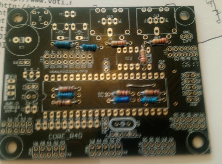
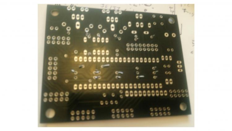
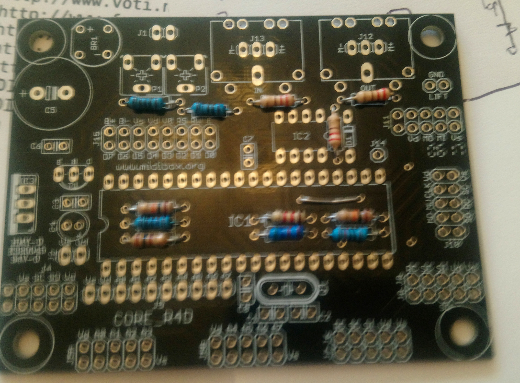
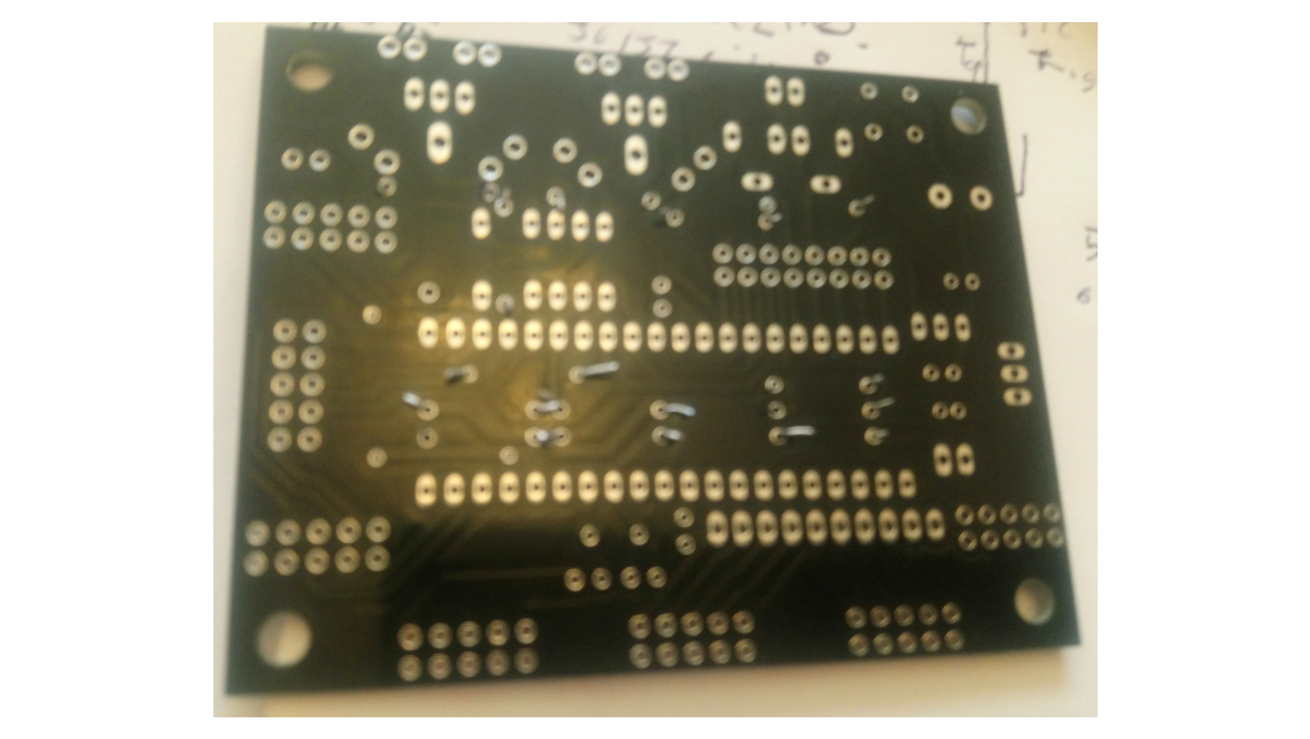
Hi latagid thanks for getting back to me! I have managed to upload the pictures. The board I guess is version 4 double sided and it says CORE_R4D on it, are any bridges needed for this board? If so where do they go? also on the first picture what are those 5 holes near the right side of the pic for, I have put a resistor bridge between 2 of them so I will have to take it out, what are the holes for? do any bridges go there? if so how do they connect? Many thanks for your invaluable help, alistair.
Where can I download modern pickit programming software fpr windows
in MIDIbox SID
Posted
Also what lines power the lcd back light? I need to check them, thanks.