
Lorcan
-
Posts
83 -
Joined
-
Last visited
Content Type
Profiles
Forums
Blogs
Gallery
Posts posted by Lorcan
-
-
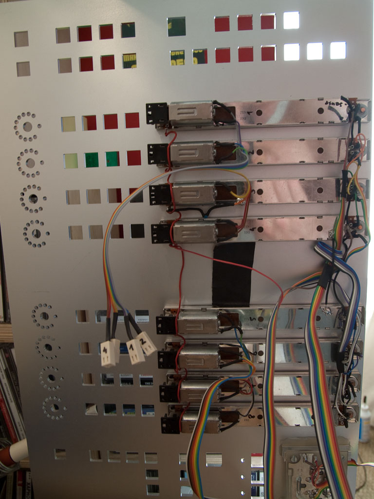
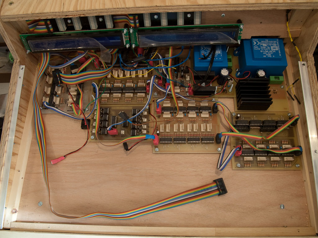
And the mandatory gutshots ...
-
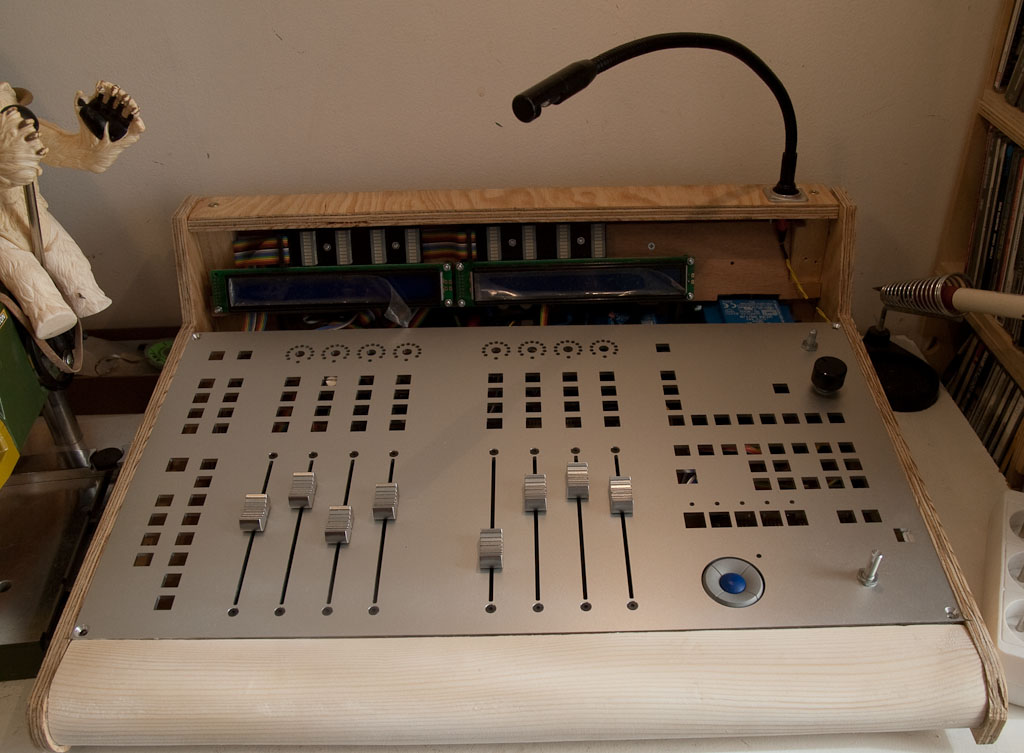
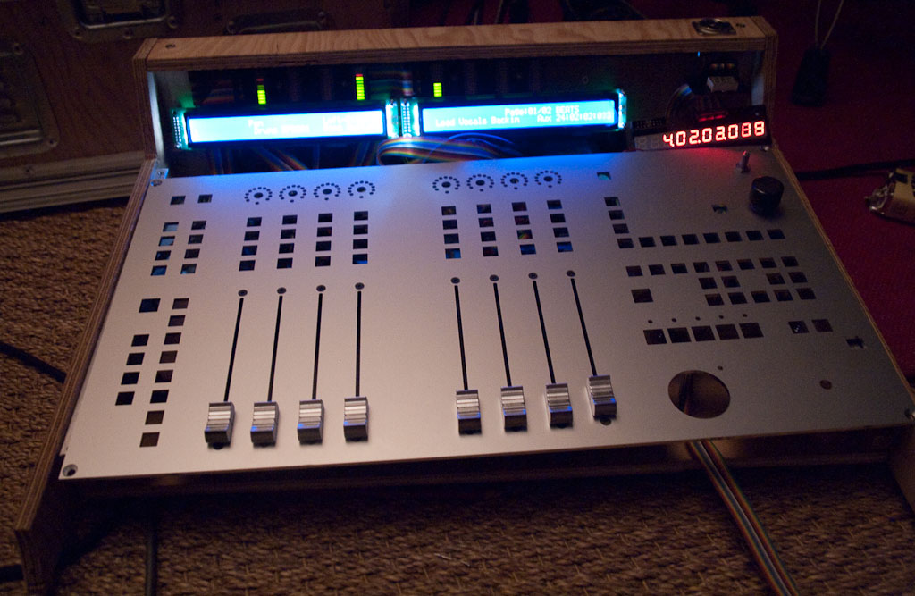
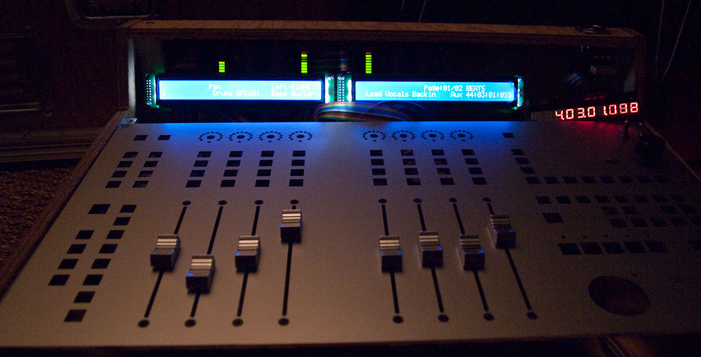
Hi, here's a few pics of my LC clone. I've designed and optimized the layout for use with Cubase, and got the panel made at Schaeffer.
There's also a little monitoring section so I have everything within arm reach.
The electronics worked great straight 'out of the shop', apart from a few minor glitches that I found out quickly.
I bought some nice illuminated buttons at digikey. They weren't cheap at around 2€ a piece, but the idea being was they allowed me to save on the labelling by inserting tiny pieces of printed transparency foil underneath the button cap.
I made quite a few custom pcbs for this and will make these available to anyone that's interested once I'm finished.
Cheers, and big thanks to all of you here, especially Thorsten of course 8)
Lorcan
-
You should check this site too, the design is newer and maybe better (haven't built myself) http://www.megadrum.info/
I built an edrum 16 that i'm not using anymore because i got myself a Roland Td-3. I should think of selling it one day, maybe
-
The original LC has an HUI emulation, but I'm quite sure the MidiBox LC 1.6 code does not implement that.
Maybe you could emulate some commands of the HUI protocol by looking at the spec and modifying the source.
I should think it's not such a big deal, as LC/HUI protocols are mostly standard midi messages.
The biggest problem IMHO would be to find drop-in replacement faders for your console with audio/position tracks that are compatible with the MF module.
-
Yes it's basically that. Just make sure you don't make a loop by connecting the gnd twice at different locations. This can go unnoticed easily if you have metallic parts fitted to a metal enclosure for example.
-
You can connect the ground directly, but try avoiding any ground loops, ie the same signal flowing through different paths, otherwise you might get noise, oscillations, etc. Best wiring for ground is called 'star wiring': all ground leads start from a unique, low resistance point. It's mandatory when there's audio going through the device, so here it's not really needed
As for the pcb, just make sure to route on the copper side (bottom), do not use any vias. Find out what cad format the shop uses.You'll have to google for a tutorial on exporting gerber files for this, or look at eagle manual. I've never done it myself (etch my pcbs at home)
-
You won't be able to control 13 motorfaders with a single core, that's because the fader handling is implemented in software and quite cpu hungry. One core can control 8, so you'll need 2 cores
-
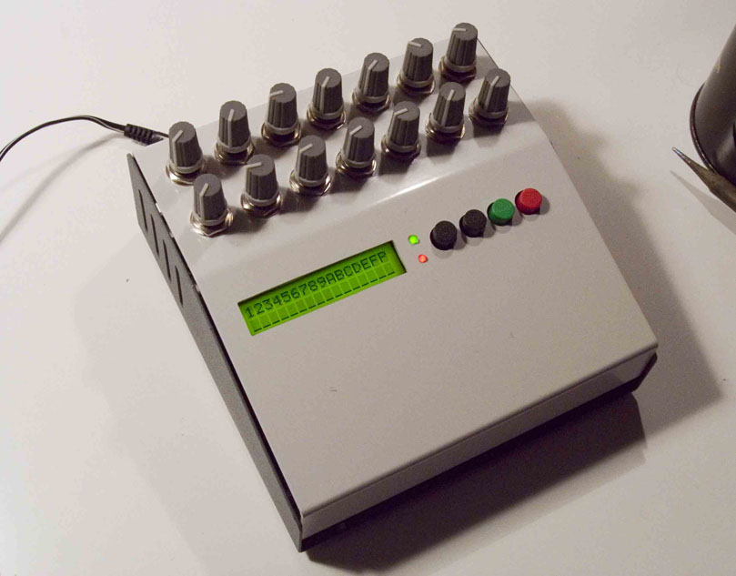
I built the edrum, it's quite good. Another project has surfaced in the meantime, which looks more advanced
-
Thanks, I try to take my time and do things well. I sometimes wish it was finished though, so I could go play music and use it :P
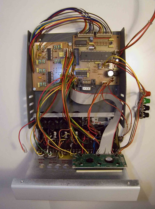
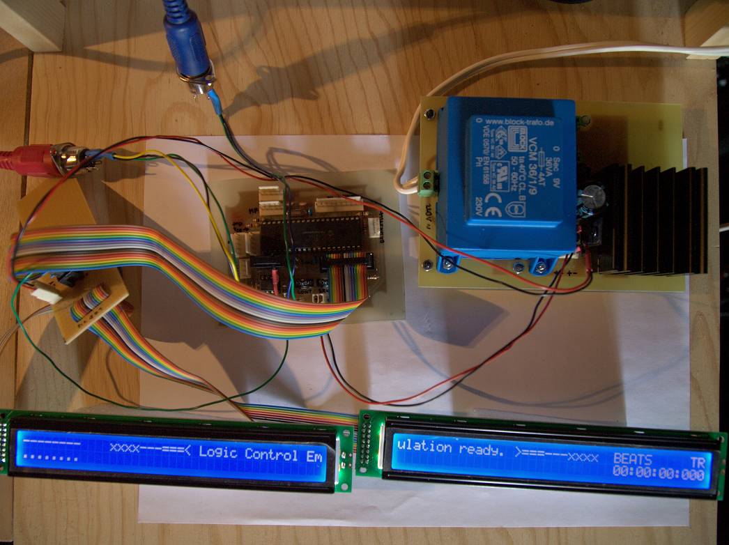
So I also did the schematic and a board for the core (8bit PIC, v3), and I was happy to find it seems to work good.
Notice the core pcb has been stripped of the power supply section as this is on a separate board to provide more power and facilitate heatsink moutinf.
Now onto the DIN/DOUTS, ledrings, vumeters, LTC ...

-
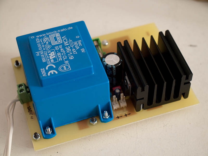
And here are the files for the 5V PSU (tried and tested), that should provide sufficient power for all modules and leds
The transfo is a Block EI 66/23 109 from reichelt (9V@4A), and the regulator is a 78t05 which is a version of the 7805 that can handle 3amps, with a proper heatsink of course

-
Hi all,
I'm currently building my own LC, and in the process, I wanted to modify the PCBs provided by Thorsten to accommodate for the connectors I bought and other things, so I provide them to the community. Maybe others will find this useful
I have also entered the schematics in Eagle to make it easier, this should prove useful to people designing custom combinations of modules.
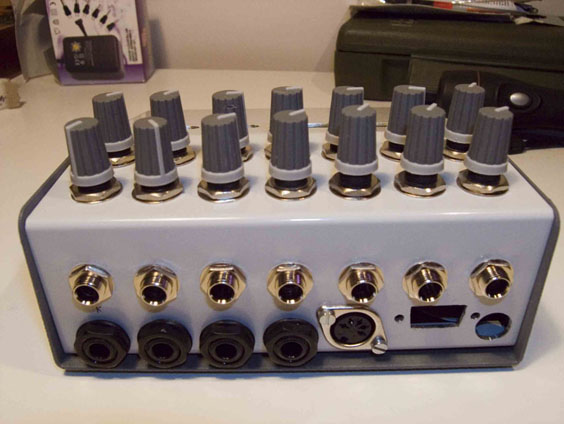
Here is the DIN x4, DOUT x4, and a 5V/3A linear PSU i made for the LC.
Connectors are the 'PSK 254' crimp-connector series from Reichelt.
The Core, MF module, and 9V PSU will follow
Cheers,
Lorcan
DIN - DOUT Schematic & Board.rar


DIN - DOUT Schematic & Board.rar
-
Well, sorry I misinterpreted your post ...
So the intent of putting one regulator / fader would be to have 1.5A current capacity/fader ?
According to the datasheet 1.5A could nearly supply 2 faders @800mA each, so 1 LM317 per fader pair should suffice
You'd need quite a hefty transformer though, that could supply 7 amps ...
One thing that seems strange is that cinchet says 'my lcd gets darker' and '5v rises to 5.4v', I would believe the rise of the 5V line should make the backlight lighter, not darker
-
I saw you're using seperate PSUs. This behavior indicates a coupling between the two supplies, so it must lie elsewhere. I'd say check for shorts or any other possible source of coupling (defective cap, blown IC)
-
I think MTE was joking about the multiple power supplies ...
Looking at the datasheet I see the max motor current stated is 800mA@10v, but I guess this is only reached if you try to stop the motor with your hand, not if the fader is moving freely.
A good idea would be to measure the normal average current consumption of the fader and see if that multiplied by 8 is more than the 317 can handle. Then you'd have a problem ...
A LM338K can handle 5amps with the right heatsink, but of course you'd need the transfo and caps of your PS to follow.
As MTE said, if you don't have a large enough heatsink the temperature protection kicks in to prevent the chip from blowing up, and the output voltage is reduced as a consequence.
-
-
I wanted to test the displays but the datasheet (http://www.lcdmodkit.com/specification/LKC-4002-B2.pdf) does not mention anything about led current / forward voltage.
I measured about 3V forward voltage for the leds b ramping up current (lowering resistor value), but I don't want to go to far and fry it. Unfortunately the brightness at the current I went to is low ...
Any ideas as to what I could do ?
Thanks
Lorcan
-
Just to say I received the displays today, and that the delivery was quick and without a glitch
Lcdmodkit answered my email and gave me a tracking n°, which unfortunately is only valid inside HK, but it's still better than no tracking at all ..
I'll report when i get to test the displays, that is when i have the other components from reichelt ready, and etched the pcbs
Cheers,
Lorcan
-
I'm not interested in the masterfader, I plan to incorporate an analog control for my monitors.
IMHO there's no real point in having the 9th fader as master, except maybe for trimming your mix in one go.
The output from the DAW is best at close to 0dBfs, otherwise you'll be losing precious bits.
My soundcard (RME Fireface) has quite a complex routing matrix (Totalmix) with an integrated zero-latency mixer, but as many people do, I'd rather trim my ouput with a pot than wasting bits.
Mind you with 24bits it doesn't make that much of a difference if you lose one or two bits
Still purists go as far as doing all the summing with a dedicated analog box (summing mixer, which costs big $$$ ???)
-
Errmm .. I guess I must have not looked closely enough :P
In fact I had seen this but also read some statements elsewhere which seemed in contradiction with this, hence my doubt.
They were probably specific to other MIOS applications.
Thanks !
-
Hi fellow MidiBoxers,
I'm at the (beta) planning stage of an 8-track Mackie MCU clone, with a few enhancements (master analog volume control, phones control, dim main out, and maybe dedicated eq soft dials). It might seem strange to want to build a Mackie Clone now, but I've seen it in a shop and thought I could do a more robust unit (the jog had popped out on the brand-new demo unit), with meters as and added bonus, customized for my use with Cubase, and expandable, thanks to Thorsten and the rest of this great community.
So I've read all the topics (yes !) in this subforum and most others too, but I would still need someone to make this clear too me:
- can I layout the buttons/led freely, ie departing from the switch->dIn and dOut->Led pin assignements indicated in the .pdf diagrams ? More precisely, looking at the setup*.asm file, I see I can enable/disable buttons and leds, but I'm not sure if i can swap the pins and then change the assignments in the setup file.
The reason I'd want to do this is to have more degrees of freedom in making custom pcbs for holding the switches, leds and ideally dOut and dIn modules altogether on one PCB, to minimize interconnects (more tidy, cheaper, even if that means more layout work for me).
- will the R4D core bring significant improvements for the LC application ? I have a PIC already, so I'm going to use MIOS8 at first anyway
Regards,
Lorcan
-
Yes, I don't know what happened, either the package got lost in the mail or the customs stopped it but 'forgot' to send a notification they had the package to me. I was getting a little paranoid at the end, when I saw the site disappear then reappear several times, leaving me no possibility to leave an evaluation.
I find these phrases on the site a bit strange though:
Purchase at FCB only if you will leave ALL 5 stars DSR.By necessity, any none 5 stars DSR giver will be blocked from future buying.
What's the point of having an evaluation system if the seller practically refuses it ?
Anyway, I'm glad to hear my case seems to be isolated
Edit: i finally received the package from fcb, 4 months after the order. Seems it's the post office/customs that should be blamed, so I gave him a refund of the refund :o
-
Just to say I added my name to the list for 18 fader ...
Hope you get better soon, Doug, and thanks for this help to others you provide
Edit: i got some faders elsewhere, and edited the list on the wiki
-
You've dealt with fcb before ?
In fact paypal took a long time, and the seller didn't want to admit the package could have got lost.
It's in ebays/paypal interest to make people confident if they want their business model, they could have tried harder in this case. But I understand that for small amounts they don't give it much attention.
-
Thanks for the tip Stryd, I just bought two 2x40 lcds with backlight for my upcoming Midibox LC
Much cheaper than online shops who sell them for circa 40€ each ...
Let's hope they don't get lost in the mail and that the seller is honest .
Last time I bought parts from ebay i never got them, and I finally got a refund from paypal after about 10 emails and 3 months. Maybe the prices were too attractive to be true
FYI the store is http://myworld.ebay.com/fcb_electronics/
It's strange he seems to get good reviews (I'm quite new at ebay)
My LC Clone, WIP
in MIDIbox HUIs
Posted
Sure, i got it from reichelt, and its' made by mec. You can't buy it ready made though, instead you have to buy the siwtches and caps and solder them to a pcb though
I can give you the pcb file i made if youn need it